Dornier 128-6 Просмотр ZIP-архива
Aircraft/Do_128-6/Documentation/files/DO128-6_D-IBUF_Main_Panel_FS9.HTM
<!DOCTYPE HTML PUBLIC "-//W3C//DTD HTML 3.2 Final//EN">
<HTML>
<HEAD>
    <TITLE>Do128-6 "D-IBUF" Description of Panel and Systems - Main Panel for FS2004</TITLE>
    <META NAME="Author" CONTENT="Mathias ElsдЯer">
    <META NAME="Date" CONTENT="Mon, 12 May 2008 12:47:36 GMT">
    <META NAME="Generator" CONTENT="XynX! NetJet Special Editon 2.40 Build 85 (Win32r)">
</HEAD>
<BODY BACKGROUND="background.jpg">
<H1><U><FONT SIZE=4><FONT FACE="Arial">4.1 Description of Main Panel</FONT></FONT></U></H1>
<P><FONT FACE="Arial">The pilot’s panel of “D-IBUF” is completely conventional,
as opposed to the copilot’s side with two Cathode Ray Tube (CRT) displays of which the
upper one with the Attitude Situation Indicator and Flight Director is marginally visible on
the small inset on the </FONT><A HREF="DO128-6_D-IBUF_History_FS9.HTM#virtual_vision_approach"
TITLE="Go to synthetic VFR approach photo"><FONT FACE="Arial">synthetic VFR approach photo</FONT></A><FONT FACE="Arial">
in the section “History of the real Do 128-6 “D-IBUF”.</FONT><BR>
<FONT FACE="Arial">Here a first overview of the complete FS2004 main panel with the Radio Panel
and Overhead Panel (only a placeholder here, it is now greatly extended). You may move directly to the detailed explanation of any item over which
the mouse pointer turns into a hand by left-clicking on it with your mouse, and you can return
to this overview by left-clicking in the detail-picture. However, general instruments which
are present in (just about) every plane are not separately explained, as for instance the altitude indicator:</FONT><BR>
<BR>
<A NAME="Main_Panel_Overview"></A><MAP NAME="Map1">
    <AREA SHAPE=RECT COORDS="717,208,829,263" TITLE="Radios">
    <AREA SHAPE=RECT COORDS="190,494,265,561" TITLE="Radio-Magnetic Indicator">
    <AREA SHAPE=RECT COORDS="779,437,829,490" TITLE="Transponder">
    <AREA SHAPE=RECT COORDS="673,437,776,540" TITLE="Radios">
    <AREA SHAPE=RECT COORDS="672,403,832,436" HREF="#acp" TITLE="Go to Audio Control Panel">
    <AREA SHAPE=RECT COORDS="423,533,446,562" HREF="#WIPERSPEED" TITLE="Go to Wiper Speed Control">
    <AREA SHAPE=RECT COORDS="378,532,422,561" HREF="#fuel_totalizer" TITLE="Go to Fuel Consumption Totalizer">
    <AREA SHAPE=RECT COORDS="188,348,268,427" HREF="#Airspeed" TITLE="Go to Airspeed Indicator">
    <AREA SHAPE=RECT COORDS="274,467,370,552" HREF="#HSI" TITLE="Go to Horizontal Situation Indicator">
    <AREA SHAPE=RECT COORDS="165,378,185,411" HREF="#flapindicator" TITLE="Go to Flap Position Indicator">
    <AREA SHAPE=RECT COORDS="459,356,562,401" HREF="#torque" TITLE="Go to Torque Indicator">
    <AREA SHAPE=RECT COORDS="459,402,562,448" HREF="#ITT" TITLE="Go to ITT Indicator">
    <AREA SHAPE=RECT COORDS="459,449,562,494" HREF="#prop_rpm" TITLE="Go to Propeller RPM Indicator">
    <AREA SHAPE=RECT COORDS="459,495,562,541" HREF="#Ng" TITLE="Go to Gas Generator RPM Indicator">
    <AREA SHAPE=RECT COORDS="566,356,670,401" HREF="#FF" TITLE="Go to Fuel Flow Indicator">
    <AREA SHAPE=RECT COORDS="566,402,670,448" HREF="#FP" TITLE="Go to Fuel Pressure Indicator">
    <AREA SHAPE=RECT COORDS="566,449,670,494" HREF="#oil" TITLE="Go to Oil Pressure / Oil Temp. Indicator">
    <AREA SHAPE=RECT COORDS="566,495,670,541" HREF="#fuel_quant" TITLE="Go to Fuel Quantity Indicator">
    <AREA SHAPE=RECT COORDS="342,276,827,308" HREF="#annunciator_panel" TITLE="Go to Annunciator Panel">
    <AREA SHAPE=RECT COORDS="129,410,181,444" HREF="#MASTER_WARNING" TITLE="Go to Master Warning / Master Caution lights">
    <AREA SHAPE=RECT COORDS="339,70,628,179" HREF="#4.1.4_Switch_Panel" TITLE="Go to Switch Panel (Overhead Panel)">
    <AREA SHAPE=RECT COORDS="138,379,163,405" HREF="DO128-6_D-IBUF_CHECK_LEGAL_FS9.HTM#Checklists"
    TITLE="Go to Checklists & useful Hints">
</MAP><IMG ALIGN=LEFT SRC="Do128-6_D-IBUF_main_panel_overview3.jpg" USEMAP="#Map1" ALT="D-IBUF Main Panel"
HEIGHT=637 WIDTH=949 BORDER=0><BR CLEAR=ALL>
<BR>
<FONT FACE="Arial"><A HREF="Do128-6_D-IBUF_FS9.htm">Back to Content</A><BR>
</FONT></P>
<H2><BR>
<U><FONT SIZE=4><FONT FACE="Arial">4.1.1 Flight Instruments</FONT></FONT></U><A NAME="4.1.1_Flight_Instruments"></A><BR>
</H2>
<P><FONT FACE="Arial">Please note that for correct display of the flight instruments all boxes
in “Extras/Settings/Instruments” must be checked and in “Extras/Settings/International”
Measuring Units must be set to “US-System”.</FONT><BR>
<BR>
<A HREF="#Main_Panel_Overview" TITLE="Back to Main Panel Overview"><IMG ALIGN=LEFT SRC="airspeed.gif"
HEIGHT=296 WIDTH=301 HSPACE=4 BORDER=0></A><FONT FACE="Arial">The Thommen </FONT><A NAME="Airspeed"></A><B><FONT FACE="Arial">Airspeed
Indicator</FONT></B><FONT FACE="Arial"> displays Indicated Airspeed in Knots.</FONT></P>
<TABLE BORDER=1 WIDTH="60%">
<TR>
    <TD VALIGN=TOP>
        <P><FONT FACE="Arial">MARKING</FONT></P></TD>
    <TD VALIGN=TOP>
        <P><FONT FACE="Arial">KIAS VALUE<BR>
        OR RANGE</FONT></P></TD>
    <TD VALIGN=TOP>
        <P><FONT FACE="Arial">SIGNIFICANCE</FONT></P></TD>
</TR>
<TR>
    <TD VALIGN=TOP>
        <P><FONT FACE="Arial">Red Line</FONT></P></TD>
    <TD VALIGN=TOP>
        <P ALIGN=CENTER><FONT FACE="Arial">63</FONT></P></TD>
    <TD VALIGN=TOP>
        <P><FONT FACE="Arial">Minimum Control Speed<BR>
        (Single Engine) V</FONT><SUB><FONT FACE="Arial">MC</FONT></SUB></P></TD>
</TR>
<TR>
    <TD VALIGN=TOP>
        <P><FONT FACE="Arial">White Arc</FONT></P></TD>
    <TD VALIGN=TOP>
        <P ALIGN=CENTER><FONT FACE="Arial">63 – 107</FONT></P></TD>
    <TD VALIGN=TOP>
        <P><FONT FACE="Arial">Flight Operation Speed (with FLAPS 2)</FONT></P></TD>
</TR>
<TR>
    <TD VALIGN=TOP>
        <P><FONT FACE="Arial">Lower Limit<BR>
        White Arc</FONT></P></TD>
    <TD VALIGN=TOP>
        <P ALIGN=CENTER><FONT FACE="Arial">63</FONT></P></TD>
    <TD VALIGN=TOP>
        <P><FONT FACE="Arial">Maximum Weight Stalling Speed<BR>
        (with FLAPS 2) V</FONT><SUB><FONT FACE="Arial">SO</FONT></SUB></P></TD>
</TR>
<TR>
    <TD VALIGN=TOP>
        <P><FONT FACE="Arial">Green Arc</FONT></P></TD>
    <TD VALIGN=TOP>
        <P ALIGN=CENTER><FONT FACE="Arial">73 – 150</FONT></P></TD>
    <TD VALIGN=TOP>
        <P><FONT FACE="Arial">Normal Operating Range</FONT></P></TD>
</TR>
<TR>
    <TD VALIGN=TOP>
        <P><FONT FACE="Arial">Lower Limit <BR>
        Green Arc</FONT></P></TD>
    <TD VALIGN=TOP>
        <P ALIGN=CENTER><FONT FACE="Arial">73</FONT></P></TD>
    <TD VALIGN=TOP>
        <P><FONT FACE="Arial">Maximum Weight Stalling Speed<BR>
        (with FLAPS UP) V</FONT><SUB><FONT FACE="Arial">S1</FONT></SUB></P></TD>
</TR>
<TR>
    <TD VALIGN=TOP>
        <P><FONT FACE="Arial">Blue Line</FONT></P></TD>
    <TD VALIGN=TOP>
        <P ALIGN=CENTER><FONT FACE="Arial">90</FONT></P></TD>
    <TD VALIGN=TOP>
        <P><FONT FACE="Arial">Best Rate of Climb Speed<BR>
        (Single Engine – FLAPS UP) V</FONT><SUB><FONT FACE="Arial">Y</FONT></SUB><FONT FACE="Arial"><BR>
        at ISA from MSL up to 11,000 ft</FONT></P></TD>
</TR>
<TR>
    <TD VALIGN=TOP>
        <P><FONT FACE="Arial">Red Line</FONT></P></TD>
    <TD VALIGN=TOP>
        <P ALIGN=CENTER><FONT FACE="Arial">150</FONT></P></TD>
    <TD VALIGN=TOP>
        <P><FONT FACE="Arial">Maximum Operating Speed V</FONT><SUB><FONT FACE="Arial">MO</FONT></SUB></P></TD>
</TR>
</TABLE><BR>

<P><A HREF="#Main_Panel_Overview" TITLE="Back to Main Panel Overview"><IMG ALIGN=LEFT SRC="HSI_overview.gif"
HEIGHT=401 WIDTH=647 BORDER=0></A><FONT FACE="Arial">The </FONT><B><FONT FACE="Arial">Horizontal
Situation Indicator</FONT></B><A NAME="HSI"></A><FONT FACE="Arial"> (HSI, gauge by Dai Griffiths)
is explained here as an exception due to its complexity and usefulness of which many flight
simulation enthusiasts are unaware.<BR>
With the Course Dial the default direction of Compass Rose may be adjusted. The course is digitally
displayed in the upper right corner with a “V” in front. The Course Indicator shows
in the direction of the VOR or ILS localizer received by the NAV1 Radio. The Deviation Bar
shows the lateral offset from the radial (VOR) or localizer beam (ILS) center. Full scale Deviation
Bar displacement (2 dots) represents the following deviation from beam center: VOR ±
10°, localizer approximately ± 2 – ½°. The small aircraft icon in
the center shows one’s position in relation to the vector or localizer beam.<BR>
The Glide Slope Indicator displays the vertical offset from the ILS glide slope. Full scale
deflection (2 dots) of the Glide Slope Indicator represents ± 0.8° from beam center.
The Heading Bug Dial allows adjustment of the Heading Bug which can be used to memorize the
next Heading you want to aim for. This Heading is digitally displayed in the upper left corner
with an “H” in front.<BR>
Red flags labeled “GS” (Glideslope) and “Heading” may show up on the left
or right margin of the gauge when either part of the HSI is not working properly, either due
to no sufficient signal available or electrical failure.<BR>
As you can see the HSI is an incredibly versatile navigation aid when you know how to interpret
and feed it with appropriate NAV1 radio Information.<BR CLEAR=ALL>
<BR>
</FONT><A HREF="#Main_Panel_Overview" TITLE="Back to Main Panel Overview"><IMG ALIGN=LEFT SRC="Flapindicator.gif"
HEIGHT=180 WIDTH=113 BORDER=0></A><FONT FACE="Arial">The </FONT><B><FONT FACE="Arial">Flap
Position Indicator</FONT></B><A NAME="flapindicator"></A><FONT FACE="Arial"> with its polished
brass front plate and screws houses a drum with three markings: UP (0° Flaps), 1 (25°
Flaps), 2 (43° Flaps). A flag with diagonal lines may cover the flap positions thus indicating
that the flaps are currently moving or no electrical power is supplied to the Flap Position
Indicator.<BR CLEAR=ALL>
<BR>
</FONT><A HREF="Do128-6_D-IBUF_FS9.htm"><FONT FACE="Arial">Back to Content</FONT></A><FONT FACE="Arial"><BR>
</FONT></P>
<H2><FONT FACE="Arial"><BR>
</FONT><U><FONT SIZE=4><FONT FACE="Arial">4.1.2 Engine Instruments</FONT></FONT></U><A NAME="4.1.2_Engine_Instruments"></A><BR>
</H2>
<P ALIGN=LEFT><FONT FACE="Arial"><A HREF="#Main_Panel_Overview" TITLE="Back to Main Panel Overview"><IMG
ALIGN=LEFT SRC="torque.gif" HEIGHT=260 WIDTH=260 BORDER=0></A>The <B>Torque Indicator </B><A
NAME="torque"></A></FONT><FONT FACE="Arial">is marked in lb – ft x 100 (1 lb ft = 1.35582 Nm) and displays
the amount of torque (turning force) transmitted via a reduction gearbox from the power turbine to the propeller. Please
note that torque at MCP (Maximum Continuous Power = approx. 400 SHP at 1900 Prop RPM) is 1108
pound - feet (upper limit of the green arc), the region marked yellow should only be used for
emergency power up to the red line which indicates the absolute maximum of 1246 lb – ft
(equivalent to approx. 450 SHP at 1900 RPM). When red line torque is attained the yellow <A
HREF="#TORQUE_LH_RH" TITLE="Go to annunciatior panel detail description">TORQUE</A> caution
lights in the annunciator panel will light up to indicate that full power is available and
to remind you to get back to the green arc range as soon as possible so as not to overheat
the engine and overstress its gearbox - thus reducing it's TBO (Time Before Overhaul).<BR CLEAR=ALL>
ATTENTION! You can overtorque and thus wreck the gearbox in a lot of clatter if you set the props to the FEATHERed state and
add too much power, so make sure you never exceed the red line limit of 1246 lb – ft!<BR></FONT>
<BR>
<A HREF="#Main_Panel_Overview" TITLE="Back to Main Panel Overview"><IMG ALIGN=LEFT SRC="ITT.gif"
HEIGHT=260 WIDTH=260 BORDER=0></A><FONT FACE="Arial">The </FONT><B><FONT FACE="Arial">Interturbine
Temperature Indicator </FONT></B><A NAME="ITT"></A><FONT FACE="Arial">(ITT) displays gas temperature between the
compressor turbine and the power turbine in °C x 100, comparable to a certain extent to
exhaust gas temperature (EGT) in a piston engine. The OFF position is marked as well as the
starting limit which is 1085°C. This means the transient starting temperature may NEVER
exceed 1085°C! The further below 12% Ng you set the condition lever to idle during engine
startup (or the further the power lever is from the ground idle position) the higher the ITT
starting transient will become – due to no sufficient airflow being developed yet inside
the combustion chamber to allow for proper continuously burning flames and enough cooling air
around the combustion chamber walls. This can damage the combustion chamber linings to the
point of disintegration and thus completely ruin a turboprop engine and as a faint possibility
even set it afire (there are two red <A HREF="#FIRE" TITLE="Go to annunciatior panel detail description"><FONT FACE="Arial">FIRE</FONT></A><FONT FACE="Arial">
warning lights in the annunciator panel), and believe me – it will happen in this FS2004
simulation if you do not adhere to the simple but important rules laid down in the starting
checklists! Normal start transient will be around 600°C.</FONT><BR>
<FONT FACE="Arial">When airflow in and around the combustion chamber has caught up with the
amount of fuel being currently burnt in there ITT will drop back down to a normal 540°C
(idle) up to 580°C at emergency power. Vice versa reducing power temporarily causes surplus
airflow that cools the combustion chamber down so ITT will drop to a low of approx. 400°C
(minimum) and then rise again as airflow is reduced to a healthy level.</FONT><BR CLEAR=ALL>
<BR>
<A HREF="#Main_Panel_Overview" TITLE="Back to Main Panel Overview"><IMG ALIGN=LEFT SRC="RPM.gif"
HEIGHT=260 WIDTH=260 BORDER=0></A><FONT FACE="Arial">The </FONT><B><FONT FACE="Arial">Propeller
RPM Indicator</FONT></B><A NAME="prop_rpm"></A><FONT FACE="Arial"> shows propeller speed and
is marked in RPM x 100. A yellowish 4 digit display at the bottom of the gauge also shows the
complete number of prop RPM to facilitate more precise readings.</FONT><BR CLEAR=ALL>
<BR>
<A HREF="#Main_Panel_Overview" TITLE="Back to Main Panel Overview"><IMG ALIGN=LEFT SRC="NG.gif"
HEIGHT=260 WIDTH=260 BORDER=0></A><FONT FACE="Arial">The </FONT><B><FONT FACE="Arial">Gas Generator
RPM Indicator</FONT></B><A NAME="Ng"></A><FONT FACE="Arial"> (Ng) indicates the percentage
of current gas generator RPM in relation to a maximum gas generator RPM of 37000 RPM.</FONT><BR>
<FONT FACE="Arial">The gas generator consists of a series of compressors which in turn are
driven by the compressor turbine. It sucks in air and compresses it to a ratio of about 1:7
(for comparison: automotive gasoline engines compress to between 1:8 and 1:12, Diesel engines
need between 1:16 and 1:23 for self combustion without help from a spark plug) and delivers
it into the combustion chambers. As stated in above section on the ITT indicator carefully
monitoring Ng during startup is crucial for successfully starting a turbine-based engine. Below
10% Ng airflow through the combustion chambers is insufficient to cool the combustion chamber
linings when combustion is initiated, the flames basically burn uncontrolled and overheat the
engine (hot start). The same thing happens if the power levers are not set to the ground idle
position before Ng reaches 51%. Idle Ng will vary in this simulation from 62% at MSL (Mean Sea Level) down to about
56% in 7000 ft and above. Adding power while climbing to higher altitudes ensures that the power output remains constant. That is the
trick with flat-rating: a potentially far more powerful turboprop (same applies to turbocharged
piston engines) engine is simply not given the amount of fuel necessary to attain that maximum
torque (and thus power) output at MSL thus leaving enough headroom to still bring the same
amount of power even in thin air at high altitudes.</FONT><BR>
<FONT FACE="Arial">Maximum Ng will be around 90 % at 1108 lb-ft of torque (MCP),
while the red line is never really reached.<BR CLEAR=ALL>
</FONT><BR>
<A HREF="#Main_Panel_Overview" TITLE="Back to Main Panel Overview"><IMG ALIGN=LEFT SRC="FF.gif"
HEIGHT=260 WIDTH=260 BORDER=0></A><FONT FACE="Arial">The second row of engine instruments starts
with the </FONT><B><FONT FACE="Arial">Fuel Flow Indicators</FONT></B><A NAME="FF"></A><FONT FACE="Arial">
which show fuel flow into the engines in pounds per hour. Fuel flow particularly in the higher
power region is rather accurate in this FS2004 simulation so you can almost fly to the book!
Idle fuel flow is too low (should be around 100 pph per engine) due to limitations in the way
FS2004 simulates the fuel flow.<BR CLEAR=ALL>
</FONT><BR>
<A HREF="#Main_Panel_Overview" TITLE="Back to Main Panel Overview"><IMG ALIGN=LEFT SRC="FP.gif"
HEIGHT=260 WIDTH=260 BORDER=0></A><B><FONT FACE="Arial">Fuel Pressure Indicators</FONT></B><A
NAME="FP"></A><FONT FACE="Arial"> will show standard 23 PSI of fuel pressure whenever the appropriate
fuel pumps are on and the fuel tank isn’t empty. Please see section </FONT><A HREF="DO128-6_D-IBUF_Pedestal_Panel_FS9.HTM#4.2.2_Fuel_Control"
TITLE="Go to Fuel Control Panel"><FONT FACE="Arial">4.2.2 Fuel Control Panel</FONT></A><FONT FACE="Arial">
for a full explanation of the fuel system of this aircraft. When fuel pressure drops below
15 PSI yellow </FONT><A HREF="#FUEL_LO_PRESS" TITLE="Go to annunciatior panel detail description"><FONT FACE="Arial">FUEL
LO PRESS</FONT></A><FONT FACE="Arial"> caution lights will illuminate in the annunciator panel.</FONT><BR
CLEAR=ALL>
<BR>
<FONT FACE="Arial">The combined </FONT><B><FONT FACE="Arial">Oil Pressure / Oil Temperature
Indicators</FONT></B><A NAME="oil"></A><FONT FACE="Arial"> are present in every aircraft with
combustion engines and are thus not separately depicted here. If both needles are level both
values are o.k. When engines are started oil pressure rises rapidly to over 40 PSI whereas
oil temperature will take some time to heat up. V.v. when turning the engine off oil pressure
will drop quickly to 0 whereas oil temperature will take a while to cool down. Whenever oil
pressure drops below 40 PSI red </FONT><A HREF="#OIL_LO_PRESS" TITLE="Go to annunciatior panel detail description"><FONT FACE="Arial">OIL
LO PRESS</FONT></A><FONT FACE="Arial"> warning lights will turn on in the annunciator panel,
accompanied by the Master Warning light’s blinking and beep. This beep will also greet
you when “stepping into” this aircraft when engines are off and electrical power
is on, as is the case with the real plane (sorry if it gets on your nerves, but the real pilots
also have to bear it, though they have the option not to put the headset on and thus not hear
the beep before they reset the Master Warning).</FONT><BR CLEAR=ALL>
<BR>
<A HREF="#Main_Panel_Overview" TITLE="Back to Main Panel Overview"><IMG ALIGN=LEFT SRC="fuel_left.gif"
HEIGHT=260 WIDTH=260 BORDER=0></A><FONT FACE="Arial">Rather important in this section are the
</FONT><B><FONT FACE="Arial">Fuel Quantity Indicators</FONT></B><A NAME="fuel_quant"></A><FONT FACE="Arial">:
The left half shows main tank fuel quantity in %, the right half external tank fuel quantity
in %. If main tank content drops below 173 lbs (approx. 20%) a red warning light at the bottom
of the instrument (Bitmap by Dai Griffiths) will remind you to start thinking about a refill
quickly! For your orientation: 100% in the main tanks equals a flyable capacity of 864 lbs
(about 500 liters or 132 gallons) of fuel each and 100% in the external tanks contain an additional
usable amount of 406 lbs (around 235 liters or 62 gallons) of fuel each. In the VC there are separate
fuel quantity indicators for the just the main tanks on the pilot's side and a dual indicator similar to the one depicted on the left
for both external fuel tanks on the co-pilot's side.</FONT><BR CLEAR=ALL>
<BR>
<A HREF="#Main_Panel_Overview" TITLE="Back to Main Panel Overview"><IMG ALIGN=LEFT SRC="fueltotalizer.gif"
HEIGHT=117 WIDTH=218 BORDER=0></A><FONT FACE="Arial">The </FONT><B><FONT FACE="Arial">Fuel
Consumption Totalizer</FONT></B><A NAME="fuel_totalizer"></A><FONT FACE="Arial"> is equiped
with a counter and registers the total amount of fuel used by both engines (in lbs). The counter
can be reset manually to 0000 by pressing the white button with a left mouseclick. However,
to prevent inadvertant resetting of the counter you must first unlock the button by a left
mouseclick on the lock lever. Another click on the lock will swivel it back into position.
The gauge memorizes its last reading when you choose another aircraft or close FS2004 so make
sure you reset the counter before each flight. If you have filled up the tanks to the brim
and after several hours of flight see the number 2500 approaching you had better find a good
place to land and refuel FAST !</FONT><BR CLEAR=ALL>
<BR>
<A HREF="#Main_Panel_Overview" TITLE="Back to Main Panel Overview"><IMG ALIGN=LEFT SRC="Wiperspeed.gif"
HEIGHT=140 WIDTH=100 BORDER=0></A><FONT FACE="Arial">The </FONT><B><FONT FACE="Arial">Wiper
Speed Control</FONT></B><A NAME="WIPERSPEED"></A><FONT FACE="Arial"> allows speed adjustment
of the animated windshield wiper of this aircraft (only present in 2D-panel mode). You do this by turning the knob from the
default low speed position clockwise toward the right via left mouseclick anywhere in upper
half of the knob. Two other possible positions indicating medium and maximum speed knob positions
are also depicted at left. A single click will turn the knob to the desired position, but you
may also drag the red indicator line around to where you want it. The desired speed will naturally
only take effect when the wiper is switched on.<BR>
One little curiousity here: Contrary to most aspects of this simulation you have a bonus here
over the real "D-IBUF": for some unknown reason Dornier correctly placed the Wiper
Speed Control in the panel but failed to wire it to the wiper motor - thus only leaving the
wiper to work at full speed </FONT><FONT FACE="Wingdings">J</FONT><BR CLEAR=ALL>
<BR>
<A HREF="#Main_Panel_Overview" TITLE="Back to Main Panel Overview"><IMG ALIGN=LEFT SRC="audio-control-panel.jpg"
HEIGHT=70 WIDTH=311 BORDER=0></A><FONT FACE="Arial">The </FONT><B><FONT FACE="Arial">Audio
Control Panel</FONT></B><A NAME="acp"></A><FONT FACE="Arial"> serves to switch on or off various
audio sources which are listed here:<BR CLEAR=ALL>
<BR>
VHF1 and VHF2: These two activate the COM1 and/or the COM2 radio. However, it is not really advisable
to activate both simulatenously as you can get quite an audio garble with two simulatneous tramissions
coming in. It is possible however to use VHF(COM)1 for communication and set VHF(COM)2 to an ATIS
frequency. In FS the ATIS facts can be displayed as a string on screen instead of as an audio broadcast,
so it is possible to temporarily turn on both VHF switches and then turn off the ATIS and just read the string.<BR>
<BR>
DME, ADF, NAV1 and NAV2: Switching on the appropriate naviagation radio/mode allows monitoring of it's Morse code
identifyer to ensure you have set the right frequency.<BR>
<BR>
MKR: Turns the Outer, Middle and Inner Marker identifier signals of an ILS on and off. These are beeps of varying speed
that tell you if you are just overflying the appropriate approach marker and thus gives an indication
of distance to the runway you are approaching. The associated marker lights are located directly above
the altimeter as you should check your altitude above each marker and compare it to the approach chart, thus
double-checking that you are on the prescribed ILS approach path. When flying from the VC it is advisable that
you turn the Marker audio on during an ILS approach as the Marker lights all but disappear below the much too
low glare shield (one of those "unfinished" things I can't do anything about...).</FONT><BR>
<BR>
<A HREF="Do128-6_D-IBUF_FS9.htm"><FONT FACE="Arial">Back to Content</FONT></A><FONT FACE="Arial">1
</FONT></P>
<H2><BR>
<FONT FACE="Arial"><FONT SIZE=4><U>4.1.3 Annunciator System</U></FONT></FONT><A NAME="4.1.3 Annunciator System"></A></H2>
<P><FONT FACE="Arial"><BR>
This FS2004 panel is fitted with an extensive and fully labelled </FONT><B><FONT FACE="Arial">annunciator
panel</FONT></B><A NAME="annunciator_panel"></A><FONT FACE="Arial">. <BR>
In the VC there is a pop-up icon between the VHF Homing Indicator and the Transponder for opening a 2D window
of the annunciator panel.<BR>
It incorporates a series of white advisory lights, green indication lights, red warning lights which show that a hazardous condition requiring
immediate corrective action exists and yellow caution lights that show when an impending possibly
dangerous condition exists that requires attention but not necessarily immediate action.</FONT><BR>
<FONT FACE="Arial">Whenever a red warning light in the annunciator panel illuminates the red
</FONT><A HREF="#MASTER_WARNING" TITLE="Go to explanation of Master Warning light"><FONT FACE="Arial">Master
Warning</FONT></A><FONT FACE="Arial"> light described further below will flash and a 1000Hz
beep will sound. Likewise a yellow caution light will cause the yellow </FONT><A HREF="#MASTER_CAUTION"
TITLE="Go to explanation of Master Caution light"><FONT FACE="Arial">Master Caution</FONT></A><FONT FACE="Arial">
light to blink. When all red respectively yellow annunciator lights are off again due to the
problem(s) having been solved the master lights will also cease to blink.</FONT><BR>
<BR>
<FONT FACE="Arial">In the following now a detailed description (from left to right) of all
annunciator displays of this Do 128-6 for FS2004:</FONT><BR>
<A HREF="#Main_Panel_Overview" TITLE="Back to Main Panel Overview"><IMG SRC="Do128-6_annunciator.gif"
HEIGHT=57 WIDTH=950 BORDER=0></A><BR>
<BR>
<FONT FACE="Arial">DIM / BRT switch: allows dimming (and v.v.) of the annunciator lights via
left mouse click. In daytime the BRT position (default) is advisable for clear readability
whereas at night the DIM position is better to reduce glare on the eyes.</FONT><BR>
<BR>
<FONT FACE="Arial">TEST button: When electrical power is on left-clicking on this button must
illuminate all annunciator lights (besides all other warning lights in the cockpit) as depicted above. They should stay on as long as you hold
the left mouse button down and will turn off again a few moments after letting go of it.</FONT><BR>
<BR>
<FONT FACE="Arial">BETA LH /RH</FONT><A NAME="BETA"></A><FONT FACE="Arial">: In flight advise
operation in </FONT><A HREF="DO128-6_D-IBUF_Pedestal_Panel_FS9.HTM#power_lever" TITLE="Go to explanation of BETA range">
<FONT FACE="Arial">BETA-range</FONT></A><FONT FACE="Arial">
and on ground additionally that reverse power can be used.</FONT><BR>
<BR>
<FONT FACE="Arial">FIRE LH / RH</FONT><A NAME="FIRE"></A><FONT FACE="Arial">: Advise that in
the left / right engine compartment the infrared detectors have been actuated. In this FS2004
Aircraft this will only be caused by excessive </FONT><A HREF="#Ng" TITLE="Go to explanation of Ng indicator"><FONT FACE="Arial">hot
start</FONT></A><FONT FACE="Arial"> due to disregarding the start checklists…</FONT><BR>
<BR>
<FONT FACE="Arial">OIL LO PRESS LH / RH</FONT><A NAME="OIL_LO_PRESS"></A><FONT FACE="Arial">:
Advise that the left / right </FONT><A HREF="#oil" TITLE="Go to explanation of engine oil pressure"><FONT FACE="Arial">engine
oil pressure</FONT></A><FONT FACE="Arial"> is less than 40 PSI. This is particularly the case
when engines are off but could also be caused by an oil leak or a defective oil pump.<BR>
</FONT><BR>
<FONT FACE="Arial">DOORWARN</FONT><A NAME="DOORWARN"></A><FONT FACE="Arial">:
Advises that passenger entrance door (SHIFT+E) is not secured for flight.
In FS-speak: Main Exit is open. In this aircraft that poses a grave danger: The inner portion of the
</FONT><A HREF="DO128-6_D-IBUF_Pedestal_Panel_FS9.HTM#flaps_handle" TITLE="Go to explanation of flap handle">
<FONT FACE="Arial">flaps</FONT></A><FONT FACE="Arial"> will collide with
an open door and become damaged and jammed. This is simulated, at least in the flight- and systems behaviour: the flaps will remain in
the position in which they were damaged by the open door, no matter what you try. Damaged flaps will naturally also
cause uneven lift and drag which will make it hard to control the aircraft. An emergency landing is highly advisable in this
case. The damage is fixed by reloading the plane into Flight Simulator.
In case you take off with door open and flaps UP you will notice a yaw tendency to the left due to the excessive drag on
the left. Above 100 KIAS the door will be blown out of it's receptacle on the fuselage and slam shut, thus also allowing
straight and level flight again.</FONT><BR>
<BR>
<FONT FACE="Arial">BATT OVERTEMP: Currently just a dummy.</FONT><BR>
<BR>
<FONT FACE="Arial">TORQUE LH / RH</FONT><A NAME="TORQUE_LH_RH"></A><FONT FACE="Arial">: Advise
that left / right torque have reached or exceeded </FONT><A HREF="#torque" TITLE="Go to explanation of torque indicator"><FONT FACE="Arial">emergency
power torque</FONT></A><FONT FACE="Arial"> (1246 lb-ft).</FONT><BR>
<BR>
<FONT FACE="Arial">LP COCK LH / RH</FONT><A NAME="LP_COCK_LH_RH"></A><FONT FACE="Arial">: Advise
that the </FONT><A HREF="DO128-6_D-IBUF_Pedestal_Panel_FS9.HTM#lp_cock" TITLE="Go to explanation of low pressure fuel cock"><FONT FACE="Arial">low
pressure fuel cock</FONT></A><FONT FACE="Arial"> of the left (right) engine is in the closed
or OFF position.</FONT><BR>
<BR>
<FONT FACE="Arial">FUEL LO PRESS LH / RH</FONT><A NAME="FUEL_LO_PRESS"></A><FONT FACE="Arial">:
Advise that the </FONT><A HREF="#FP" TITLE="Go to explanation of fuel pressure"><FONT FACE="Arial">fuel
pressure</FONT></A><FONT FACE="Arial"> of the left / right fuel system is below 15 PSI (fuel
pumps off or tanks empty).</FONT><BR>
<BR>
<FONT FACE="Arial">EXT. TANK TRANS LH / RH</FONT><A NAME="EXT_TANK_TRANS"></A><FONT FACE="Arial">:
Advise that the left / right </FONT><A HREF="DO128-6_D-IBUF_Pedestal_Panel_FS9.HTM#ext_tank_sw"
TITLE="Go to explanation of external tank transfer pump switch "><FONT FACE="Arial">external
tank transfer pump switch</FONT></A><FONT FACE="Arial"> is on but the LH / RH external tank
is empty.</FONT><BR>
<BR>
<FONT FACE="Arial">IGN START LH / RH</FONT><A NAME="IGN_START"></A><FONT FACE="Arial">: Advise
that the left / right </FONT><A HREF="DO128-6_D-IBUF_Pedestal_Panel_FS9.HTM#4.2.3_Engine_Starting"
TITLE="Go to explanation of engine starting"><FONT FACE="Arial">engine starter cycle</FONT></A><FONT FACE="Arial">
is engaged (START - in this case annunciator light will blink intermittently due to FS2004
interrupting the starter cycle every few seconds) or </FONT> <A HREF="DO128-6_D-IBUF_Pedestal_Panel_FS9.HTM#Manual_Ignition"
TITLE="Got to explanation of manual ignition"><FONT FACE="Arial">manual ignition</FONT></A><FONT FACE="Arial">
is activated.</FONT><BR>
<BR>
<FONT FACE="Arial">GEN LH / RH</FONT><A NAME="GEN"></A><FONT FACE="Arial">: Advise that the
left (right) </FONT><A HREF="#GEN_SWITCH" TITLE="Go to explanation of Generator Switches"><FONT FACE="Arial">generator
switch</FONT></A> <FONT FACE="Arial"> is off or a left (right) generator malfunction exists
(i.e. left (right) engine is off).</FONT><BR>
<BR>
<FONT FACE="Arial">PITOT HTR 1</FONT><A NAME="PITOT_HTR"></A><FONT FACE="Arial">: Advises that
the heater of the </FONT><A HREF="#PITOT" TITLE="Go to explanation of pitot tube"><FONT FACE="Arial">pitot
static system</FONT></A><FONT FACE="Arial"> (necessary for airspeed measurement) is not switched
on.</FONT><BR>
<BR>
<FONT FACE="Arial">BATT</FONT><A NAME="BATT"></A><FONT FACE="Arial">: Advises that the </FONT><A
HREF="#BATTERY" TITLE="Go to explanation of Battery Switch"><FONT FACE="Arial">battery</FONT></A>
<FONT FACE="Arial"> is not connected to the electrical system, i.e. is not switched on.</FONT><BR>
<BR>
<FONT FACE="Arial">INERTIA ON LH / RH</FONT><A NAME="INERTIA"></A><FONT FACE="Arial">: Indicates bypass operation of the </FONT><A
HREF="#INERTIA_SW" TITLE="Go to explanation of inertial separator system"><FONT FACE="Arial">inertial separator system</FONT></A>
<FONT FACE="Arial"> of the left (right) engine. Verification of the left (right) indication can can be checked by observing </FONT>
<A HREF="#torque" TITLE="Go to explanation of torque indicator"><FONT FACE="Arial">left (right)
engine torque</FONT></A><FONT FACE="Arial"> decreases during bypass operation.</FONT><BR>
<BR>
<BR>
<BR>
<A HREF="#Main_Panel_Overview" TITLE="Back to Main Panel Overview"><IMG ALIGN=LEFT SRC="Do128-6_master_warning_lights.gif"
HEIGHT=166 WIDTH=258 BORDER=0></A><FONT FACE="Arial">The red </FONT><B><FONT FACE="Arial">Master
Warning</FONT></B><A NAME="#MASTER_WARNING"></A><FONT FACE="Arial"> light will start to flash
and a 1000Hz beep will sound whenever a hazardous condition requiring immediate corrective
action exists, i.e. one of the red warning lights in the annunciator panel illuminate. This
will continue until either the hazardous condition has been corrected and all red warning lights
in the annunciator panel are off or by left-clicking on the master warning light to reset it.
It will then stay off until another red warning light in the annunciator panel illuminates.<BR>
ATTENTION! Unlike with the default FS2004 panels clicking on the Master Warning light will
not open an additional annunciator panel as this is built into the main 2D-panel.</FONT><BR>
<BR>
<FONT FACE="Arial">Likewise the yellow </FONT><B><FONT FACE="Arial">Master Caution</FONT></B><A
NAME="#MASTER_CAUTION"></A><FONT FACE="Arial"> light will start to flash whenever an impending
possibly dangerous condition exists requiring attention but not necessarily immediate action.
No audio tone is activated. Again it will continue to flash until either all yellow caution
lights in the annunciator panel are off again or may be reset in the same manner as the master
warning light.<BR>
ATTENTION! Unlike with the default FS2004 panels clicking on the Master Caution light will
not open an additional annunciator panel as this is built into the main 2D-panel.</FONT><BR>
<BR>
<FONT FACE="Arial">ATTENTION! Both lights (including the beep) may greet you when first initialising
this panel when for example the engines are off (which will illuminate the OIL LO PRESS LH
/ RH warning lights) or any other condition that illuminates a yellow caution light exists.
This is not a bug but pure reality as in the real plane. Just left-click on the master lights
to silence the beep and extinguish them.</FONT><BR>
<BR>
<A HREF="Do128-6_D-IBUF_FS9.htm"><FONT FACE="Arial">Back to Content</FONT></A><FONT FACE="Arial"><BR>
</FONT></P>
<P><BR>
<B><U><FONT SIZE=4><FONT FACE="Arial">4.1.4 Switch Panel (Overhead Panel)</FONT></FONT></U></B><A
NAME="#4.1.4_Switch_Panel"></A><BR>
<BR>
<FONT FACE="Arial">This Overhead Panel now is only marginally simplified from the original plane's switch
panel due to a few limitations still sticking around in FS2004, like no fire detection and extinguishing system or still rather basic electrical system. <BR>
In the VC the Overhead Panel is mounted where you would come to expect it - above your head </FONT><FONT FACE="Wingdings">J</FONT><BR>
<FONT FACE="Arial">Below is a listing of the various functions.</FONT><BR>
<BR>
<A HREF="#Main_Panel_Overview" TITLE="Back to Main Panel Overview"><IMG SRC="overhead_panel.jpg"
HEIGHT=725 WIDTH=731 BORDER=0></A><BR>
<BR>
<B><FONT FACE="Arial">ANTI-ICING / HEATING</FONT></B><BR>
<FONT FACE="Arial">PITOT: <A NAME="PITOT"></A></FONT><FONT FACE="Arial">Switches pitot tube heating on and off.
The pitot tube is the black angled tube protruding forward from the upper front corner of the
vertical stabilizer fin (in this research plane's current incarnation it actually sports twin tubes up there for redundancy purposes).
It has an opening in it’s front end and some openings along it’s
sides which are connected to the airspeed indicator with tubes. When the aircraft picks up
speed ram air pressure builds up at the front end but the side openings remain under the static
ambient pressure. The pressure difference between the two locations is displayed as Indicated
Airspeed in the airspeed indicator. The higher the airspeed the higher this pressure difference
is. It remains relatively constant despite changes in ambient air pressure due to altitude
changes. For the airspeed indicator to work properly it is of utmost importance that all openings
of the pitot tube are unrestricted by dirt, insects and ice. To prevent the latter from forming
the pitot tube is equipped with an electrical heating system which must be switched on for
take-off and landing as well as when flying in icing conditions. If electrical power is on
but the pitot heater is not a yellow caution light marked "<A HREF="#PITOT_HTR" TITLE="Go to explanation of PITOT HTR 1 caution light">PITOT
HTR 1</A>" in the annunciator panel will remind you to turn it on.<BR>
<BR>
<FONT FACE="Arial">PROP: Switches the heating pads on the leading edges of the propellers on and
off. A blue light in the top left of the pilot's and top right of the co-pilot's (VC only) panel will light up when prop-heating is on (they can also be pressed in this simulation to
switch prop heating on and off), and two amp-meters at the bottom right edge of the co-pilot's panel (VC only) will read around
16A each when the electrical system is working properly.</FONT><BR>
<BR>
<FONT FACE="Arial"><A NAME="INERTIA_SW"></A>INTAKE and INTERTIA: Both switches are linked because FS2004 does not simulate heated air intakes for
turboprop engines yet. Operation of inertial seperator flaps at the end of the air intake ducts below the engines however are simulated -
at least their effect on engine performance is: <BR>
At the end of this duct the air flow is directed upwards and forced to completely
reverse it's course due to the engine design. During take-off from dirt strips with a high likelyhood of debris (particularly stones) being
sucked into the air intakes - or while flying through excessively severe rain, snow or hail - a flap at the end of the duct is
opened, thus allowing heavy objects to exit / bypass directly out the back before they can be sucked into the engine proper. However,
as the air now also struggles to get around that bend without the help of the flap there is a slight power loss when these switches are
turned on. The flap can be seen when you look straight  into the air duct.<BR>
A green indication light marked "<A HREF="#INERTIA" TITLE="Go to explanation of INERTIA ON indication light">INERTIA ON
LH / RH</A>" in the annunciator panel is lighted when the inertial sepparator system is turned on.</FONT><BR>
<BR>
<FONT FACE="Arial">SURF: Switches the de-icing boots on the leading edges of the main wing
and elevator on and off. In the real plane this is done periodically by inflating de-icing boots (the black patches on the leading edge of wing and elevator)
with bleed air taken from the engines to blast off ice accumulations. In FS we only have the electrical heating option...</FONT><BR>
<BR>
<FONT FACE="Arial">BLEED AIR and WSHLD: Only non-functional bitmaps.</FONT><BR>
<BR>
<B><FONT FACE="Arial">LIGHTS</FONT></B><BR>
<FONT FACE="Arial">WIPER: Switches the animated windscreen wiper on and off (2D panel only. The wipers of the outside model are not animated).
In the PARK position the wiper completes its cycle and switches off upon reaching its parking position by the centerpost.
Wiper speed may be adjusted with the <A HREF="#WIPERSPEED" TITLE="Go to explanation of wiper speed control">wiper
speed control knob</A> situated below the DME on the main panel. Without electricity the wiper
will freeze in its current position as it is electrically operated.</FONT><BR>
<BR>
<FONT FACE="Arial">INSTR.: Switches instrument lighting on and off. In the 2D-panel you get the old-fashioned illuminated panel effect,
in the VC two spotlights in the roof bathe the cockpit in light. The various annunciator lights do not shine in the dark.</FONT><BR>
<BR>
<FONT FACE="Arial">LAND: Switches landing lights on and off. This aircraft is equipped with
two wing-tip mounted landing lights. This switch normally resides in the yoke pylons.</FONT><BR>
<BR>
<FONT FACE="Arial">ANTI-COLL: Switches the red anti-collision light (also called beacon) located
on top of the balancing tab of the rudder on and off.</FONT><BR>
<BR>
<FONT FACE="Arial">NAV: Switches the navigation lights on and off. They consist of a red light
in the left wing tip, a green light in the right wing tip and a white tail light at the end
of the tail cone. By the way - this navigation light pattern was directly adopted from the
maritime lighting configuration, as are many other aspects of aviation such as titles like
Captain and First Officer or the usage of nautical miles and knots for distance and speed.</FONT><BR>
<BR>
<FONT FACE="Arial">STROB: Switches the three white strobe lights on and off which are located
in the same places as the navigation lights.</FONT><BR>
<BR>
<FONT FACE="Arial">SURF: Switches a light located in the left fuselage wall on and off that illuminates the left wing leading edge.
In the real plane this is necessary in icing conditions at night to check the amount of ice buildup to determine the right time for inflating the
de-icing boots. If the boots are inflated too early the ice sheet is so thin that it can still follow the contour of the inflated boot and stays put.
If inflating is belated the ice cover is so thick that it can longer be blasted off...
In FS the light also additionally lights the VC because I could not make it a directional spotlight.</FONT><BR>
<BR>
<FONT FACE="Arial">SEAT BELT / NO SMOKE: Not wired in this aircraft - not in the real one, not in the simulation.</FONT><BR>
<BR>
<B><FONT FACE="Arial">TRIM etc.</FONT></B><BR>
<FONT FACE="Arial">PITCH TRIM: The pitch trim wheel and indicator. Should be set to about
7° UP for takeoff. Trim changes can be made via left mouseclick over the appropriate region you want to trim to
or with your mouse wheel. The default keyboard hotkeys are also available.</FONT><BR>
<BR>
<FONT FACE="Arial">INVERTER and NON ESS: Only non-functional bitmaps.</FONT><BR>
<BR>
<FONT FACE="Arial">RUDDER: The rudder trim wheel and indicator. You will most likely need this
if one engine becomes inoperative in flight, but can also be helpful to counter the FS2004
"p-factor" if you haven't set it to zero anyway. Again trim changes can be made via left mouseclick over the appropriate
region you want to trim to or with your mouse wheel, and keyboard hotkeys are also available.</FONT><BR>
<BR>
<B><FONT FACE="Arial">Electrical</FONT></B><BR>
<FONT FACE="Arial">GENERATOR LH and GENERATOR RH: <A NAME="GEN_SWITCH"></A></FONT><FONT FACE="Arial">FS2004 providing something
worthy of the name "electrical system" the LH and RH generators may be switched on
and off here. Ensure you switch on the generator of an engine as soon as you have completed
its startup cycle to load the battery. This effect is visible in the loadmeter located in the
lower left corner of the main panel - the indicator should move up some way from the lower
OFF position. When electrical power is available but the generators are not working yellow
caution lights marked "<A HREF="#GEN" TITLE="Go to explanation of GEN LH / RH caution lights">GEN
LH</A>" resp. "<A HREF="#GEN" TITLE="Go to explanation of GEN LH / RH caution lights">GEN
RH</A>" in the annunciator panel will inform you of this.<BR>
<BR>
<FONT FACE="Arial">BATTERY and MASTER: <A NAME="BATTERY"></A></FONT><FONT FACE="Arial">Switches battery power on and off. Ensure
you start at least one engine and switch on its generator ASAP after it is running to ensure
your battery doesn't run flat. In this aircraft you have about 5 minutes before you run out
of "juice" (another one of the few still lingering FS2004 anomalies...). If you switch
off the battery while at least one generator is generating power a yellow caution light marked
"<A HREF="#BATT" TITLE="Go to explanation of BATT caution light">BATT</A>" in the
annunciator panel will illuminate to make sure you don't forget you are running solely on generator
power. The MASTER switch is identical in function to the BATTERY switch in FS2004.<BR>
<FONT FACE="Arial"><B>CAUTION! Many flight- and all engine instruments including the starters plus a number of systems
like flaps of this aircraft rely on electrical power to drive them, so it is advisable to take
good care of your battery!</B></FONT><BR>
<BR>
<FONT FACE="Arial">AVIONICS: Switches avionics power on and off. Radios and the GPS rely on this power.</FONT><BR>
<BR>
<A HREF="Do128-6_D-IBUF_FS9.htm"><FONT FACE="Arial">Back to Content</FONT></A><BR>
<BR>
<FONT FACE="Arial"><BR>
<BR>
<BR>
<BR>
<BR>
<BR>
<BR>
<BR>
<BR>
<BR>
<BR>
<BR>
<BR>
<BR>
<BR>
<BR>
<BR>
<BR>
<BR>
<BR>
<BR>
</FONT></P>
<P></P>
</BODY>
</HTML>
24447-do1286v5.zip
| Имя файла | Дата | Размер |
|---|---|---|
| Aircraft/Do_128-6/ | 23.08.2008 23:03 | |
| Aircraft/Do_128-6/Aircraft.cfg | 23.08.2008 15:53 | 15 KB |
| Aircraft/Do_128-6/DO_128-6_WHEELS_CHECK.htm | 21.08.2008 21:59 | 59 KB |
| Aircraft/Do_128-6/DO_128-6_WHEELS_REF.htm | 21.08.2008 21:28 | 10 KB |
| Aircraft/Do_128-6/Do128-6_FS2004.air | 01.06.2008 03:01 | 15 KB |
| Aircraft/Do_128-6/do1286P5.gif | 23.08.2008 16:41 | 13 KB |
| Aircraft/Do_128-6/do1286V5.gif | 23.08.2008 15:40 | 9 KB |
| Aircraft/Do_128-6/Documentation/ | 23.08.2008 23:03 | |
| Aircraft/Do_128-6/Documentation/Do128-6_D-IBUF_Documentation.htm | 22.12.2006 03:48 | 2 KB |
| Aircraft/Do_128-6/Documentation/F16 Air Show Tour Panel_V2 Instructions.pdf | 29.04.2008 02:19 | 851 KB |
| Aircraft/Do_128-6/Documentation/files/ | 23.08.2008 23:03 | |
| Aircraft/Do_128-6/Documentation/files/Abbreviations_and_Reference.htm | 23.08.2008 20:04 | 106 KB |
| Aircraft/Do_128-6/Documentation/files/airspeed.gif | 09.05.2001 23:31 | 32 KB |
| Aircraft/Do_128-6/Documentation/files/Altmuehltal_digital.jpg | 05.06.2001 12:32 | 8 KB |
| Aircraft/Do_128-6/Documentation/files/anig.gif | 08.03.2000 18:49 | 38 KB |
| Aircraft/Do_128-6/Documentation/files/background.jpg | 11.01.2002 02:53 | 27 KB |
| Aircraft/Do_128-6/Documentation/files/contact.gif | 23.08.2008 18:58 | 2 KB |
| Aircraft/Do_128-6/Documentation/files/D-IBUF_compare.gif | 30.03.2008 03:36 | 183 KB |
| Aircraft/Do_128-6/Documentation/files/D-IBUF_compare_panel.jpg | 04.04.2008 02:43 | 129 KB |
| Aircraft/Do_128-6/Documentation/files/D-IBUF_compare_rollout.jpg | 04.11.2002 01:11 | 78 KB |
| Aircraft/Do_128-6/Documentation/files/D-IBUF_computer_racks.jpg | 27.05.2001 03:35 | 9 KB |
| Aircraft/Do_128-6/Documentation/files/D-IBUF_Demonstrator2.jpg | 13.10.2001 23:23 | 52 KB |
| Aircraft/Do_128-6/Documentation/files/D-IBUF_Homepage_screenshot.jpg | 30.03.2008 01:51 | 27 KB |
| Aircraft/Do_128-6/Documentation/files/D-IBUF_ski.jpg | 30.05.2001 02:59 | 23 KB |
| Aircraft/Do_128-6/Documentation/files/do128_bi.gif | 17.01.2002 05:09 | 161 KB |
| Aircraft/Do_128-6/Documentation/files/Do128-6_annunciator.gif | 06.04.2008 02:27 | 20 KB |
| Aircraft/Do_128-6/Documentation/files/Do128-6_D-IBUF_boost_pump.gif | 17.04.2001 02:27 | 5 KB |
| Aircraft/Do_128-6/Documentation/files/DO128-6_D-IBUF_CHECK_LEGAL_FS9.HTM | 23.08.2008 19:44 | 43 KB |
| Aircraft/Do_128-6/Documentation/files/DO128-6_D-IBUF_CHECK_LEGAL_FS9_d.HTM | 23.08.2008 19:15 | 49 KB |
| Aircraft/Do_128-6/Documentation/files/Do128-6_D-IBUF_cond_lever_range.jpg | 02.11.2002 18:14 | 6 KB |
| Aircraft/Do_128-6/Documentation/files/Do128-6_D-IBUF_crossfeed.gif | 17.04.2001 05:18 | 4 KB |
| Aircraft/Do_128-6/Documentation/files/Do128-6_D-IBUF_flap_handle.jpg | 12.07.2002 21:53 | 8 KB |
| Aircraft/Do_128-6/Documentation/files/Do128-6_D-IBUF_FS9.htm | 23.08.2008 18:49 | 7 KB |
| Aircraft/Do_128-6/Documentation/files/Do128-6_D-IBUF_FS9_d.htm | 23.08.2008 20:00 | 7 KB |
| Aircraft/Do_128-6/Documentation/files/DO128-6_D-IBUF_History_FS9.HTM | 24.08.2008 16:55 | 17 KB |
| Aircraft/Do_128-6/Documentation/files/DO128-6_D-IBUF_History_FS9_d.HTM | 25.08.2008 01:22 | 18 KB |
| Aircraft/Do_128-6/Documentation/files/Do128-6_D-IBUF_LP_cock.gif | 12.07.2002 22:11 | 11 KB |
| Aircraft/Do_128-6/Documentation/files/DO128-6_D-IBUF_Main_Panel_FS9.HTM | 25.08.2008 00:49 | 45 KB |
| Aircraft/Do_128-6/Documentation/files/DO128-6_D-IBUF_Main_Panel_FS9_d.htm | 25.08.2008 01:06 | 50 KB |
| Aircraft/Do_128-6/Documentation/files/Do128-6_D-IBUF_main_panel_overview3.jpg | 25.08.2008 00:05 | 131 KB |
| Aircraft/Do_128-6/Documentation/files/Do128-6_D-IBUF_main_panel_overview3_d.jpg | 25.08.2008 00:34 | 132 KB |
| Aircraft/Do_128-6/Documentation/files/DO128-6_D-IBUF_Pedestal_Panel_FS9.HTM | 09.06.2008 02:20 | 23 KB |
| Aircraft/Do_128-6/Documentation/files/DO128-6_D-IBUF_Pedestal_Panel_FS9_d.HTM | 09.06.2008 02:20 | 26 KB |
| Aircraft/Do_128-6/Documentation/files/Do128-6_D-IBUF_power_lever_range.jpg | 02.11.2002 18:09 | 17 KB |
| Aircraft/Do_128-6/Documentation/files/DO128-6_D-IBUF_PREREQUISITS_FS9.HTM | 22.08.2008 03:09 | 3 KB |
| Aircraft/Do_128-6/Documentation/files/DO128-6_D-IBUF_PREREQUISITS_FS9_d.HTM | 22.08.2008 03:09 | 3 KB |
| Aircraft/Do_128-6/Documentation/files/Do128-6_D-IBUF_prop_lever_range.jpg | 02.11.2002 18:11 | 11 KB |
| Aircraft/Do_128-6/Documentation/files/Do128-6_D-IBUF_Throttle-Fuel-Start.jpg | 05.11.2002 00:40 | 134 KB |
| Aircraft/Do_128-6/Documentation/files/Do128-6_D-IBUF_Throttle-Fuel-Start_d.jpg | 05.11.2002 01:26 | 154 KB |
| Aircraft/Do_128-6/Documentation/files/Do128-6_D-IBUF_transfer_pump.gif | 17.04.2001 02:29 | 5 KB |
| Aircraft/Do_128-6/Documentation/files/DO128-6_D-IBUF_VC_FS9.HTM | 12.05.2008 01:30 | 7 KB |
| Aircraft/Do_128-6/Documentation/files/DO128-6_D-IBUF_VC_FS9_d.HTM | 12.05.2008 01:31 | 8 KB |
| Aircraft/Do_128-6/Documentation/files/DO128-6_D-IBUF_VIRTUAL_HISTORY_FS9.HTM | 12.05.2008 14:21 | 8 KB |
| Aircraft/Do_128-6/Documentation/files/DO128-6_D-IBUF_VIRTUAL_HISTORY_FS9_d.HTM | 12.05.2008 14:20 | 9 KB |
| Aircraft/Do_128-6/Documentation/files/Do128-6_master_warning_lights.gif | 01.03.2003 17:18 | 11 KB |
| Aircraft/Do_128-6/Documentation/files/Do128-6_three_view.jpg | 05.06.2001 23:15 | 52 KB |
| Aircraft/Do_128-6/Documentation/files/Do28B1.jpg | 05.06.2001 23:07 | 16 KB |
| Aircraft/Do_128-6/Documentation/files/Do28D-X5_Turbo-Skyservant.jpg | 05.06.2001 12:38 | 17 KB |
| Aircraft/Do_128-6/Documentation/files/Do28D-X5_Turbo-Skyservant_+_Do28D.jpg | 27.05.2001 03:35 | 27 KB |
| Aircraft/Do_128-6/Documentation/files/Dornier_128-6.gif | 05.06.2001 23:19 | 28 KB |
| Aircraft/Do_128-6/Documentation/files/FF.gif | 13.05.2001 22:10 | 15 KB |
| Aircraft/Do_128-6/Documentation/files/Flapindicator.gif | 02.11.2002 18:20 | 3 KB |
| Aircraft/Do_128-6/Documentation/files/FP.gif | 13.05.2001 22:20 | 15 KB |
| Aircraft/Do_128-6/Documentation/files/fuel_left.gif | 13.07.2002 03:47 | 19 KB |
| Aircraft/Do_128-6/Documentation/files/fueltotalizer.gif | 06.01.2002 19:32 | 35 KB |
| Aircraft/Do_128-6/Documentation/files/germany.gif | 28.08.2002 02:30 | 6 KB |
| Aircraft/Do_128-6/Documentation/files/HSI_overview.gif | 27.05.2001 03:35 | 52 KB |
| Aircraft/Do_128-6/Documentation/files/HSI_Uebersicht.gif | 04.08.2002 02:20 | 57 KB |
| Aircraft/Do_128-6/Documentation/files/Icon_SPEEDS.bmp | 11.08.2008 13:01 | 1 KB |
| Aircraft/Do_128-6/Documentation/files/ITT.gif | 13.05.2001 22:10 | 17 KB |
| Aircraft/Do_128-6/Documentation/files/lb244.gif | 17.12.2002 00:28 | 44 KB |
| Aircraft/Do_128-6/Documentation/files/NG.gif | 25.05.2001 20:46 | 15 KB |
| Aircraft/Do_128-6/Documentation/files/overhead_panel.jpg | 05.04.2008 22:43 | 55 KB |
| Aircraft/Do_128-6/Documentation/files/POH p5-21 Stall speeds engines idling.jpg | 29.07.2008 03:26 | 374 KB |
| Aircraft/Do_128-6/Documentation/files/POH p5-23 Takeoff speeds flaps up.jpg | 29.07.2008 03:36 | 391 KB |
| Aircraft/Do_128-6/Documentation/files/POH p5-24 Takeoff speeds flaps 1.jpg | 29.07.2008 03:42 | 391 KB |
| Aircraft/Do_128-6/Documentation/files/POH p5-41 Best rate-of-climb speeds two engines.jpg | 29.07.2008 03:46 | 338 KB |
| Aircraft/Do_128-6/Documentation/files/POH p5-43 Best rate-of-climb speeds one engine.jpg | 11.08.2008 21:14 | 304 KB |
| Aircraft/Do_128-6/Documentation/files/POH p9-15 VHF Homing System Becker ZVG2002.jpg | 01.05.2008 04:13 | 326 KB |
| Aircraft/Do_128-6/Documentation/files/POH p9-16 VHF Homing System Becker ZVG2002.jpg | 01.05.2008 04:13 | 225 KB |
| Aircraft/Do_128-6/Documentation/files/POH p9-17 VHF Homing System Becker ZVG2002.jpg | 01.05.2008 15:21 | 118 KB |
| Aircraft/Do_128-6/Documentation/files/POH p9-59 Radio Altimeter System Sperry AA-300.jpg | 01.05.2008 03:12 | 245 KB |
| Aircraft/Do_128-6/Documentation/files/POH p9-60 Radio Altimeter System Sperry AA-300.jpg | 01.05.2008 15:45 | 206 KB |
| Aircraft/Do_128-6/Documentation/files/POH Page 7-7 Instrument Panel.jpg | 01.05.2008 21:37 | 344 KB |
| Aircraft/Do_128-6/Documentation/files/PT6A-110.jpg | 05.06.2001 12:46 | 39 KB |
| Aircraft/Do_128-6/Documentation/files/Radar.jpg | 01.05.2008 22:11 | 34 KB |
| Aircraft/Do_128-6/Documentation/files/Radar_d.jpg | 12.05.2008 01:23 | 35 KB |
| Aircraft/Do_128-6/Documentation/files/Realism_Settings.jpg | 04.04.2008 03:10 | 64 KB |
| Aircraft/Do_128-6/Documentation/files/Realism_Settings_d.jpg | 23.06.2008 01:55 | 61 KB |
| Aircraft/Do_128-6/Documentation/files/RPM.gif | 13.05.2001 22:03 | 16 KB |
| Aircraft/Do_128-6/Documentation/files/schema-pt6a.gif | 17.12.2002 00:29 | 7 KB |
| Aircraft/Do_128-6/Documentation/files/Speedcharts.htm | 20.08.2008 16:52 | 2 KB |
| Aircraft/Do_128-6/Documentation/files/start.gif | 08.05.2001 23:34 | 12 KB |
| Aircraft/Do_128-6/Documentation/files/Synthetic_Vision_Approach.jpg | 30.05.2001 02:55 | 40 KB |
| Aircraft/Do_128-6/Documentation/files/torque.gif | 13.05.2001 22:08 | 17 KB |
| Aircraft/Do_128-6/Documentation/files/uk.gif | 28.08.2002 02:30 | 9 KB |
| Aircraft/Do_128-6/Documentation/files/Wiperspeed.gif | 07.01.2002 01:13 | 5 KB |
| Aircraft/Do_128-6/Documentation/Info.txt | 27.04.2006 16:29 | 9 KB |
| Aircraft/Do_128-6/Documentation/Legal Notice.txt | 13.01.2006 18:10 | 608 B |
| Aircraft/Do_128-6/Documentation/RadarApproaches.doc | 27.04.2006 17:29 | 84 KB |
| Aircraft/Do_128-6/INSTALL.txt | 26.08.2008 01:35 | 7 KB |
| Aircraft/Do_128-6/Installation_Deutsch.txt | 26.08.2008 01:35 | 8 KB |
| Aircraft/Do_128-6/model/ | 23.08.2008 23:03 | |
| Aircraft/Do_128-6/model/DO 128-6 D-IBUF FS2K2 v1.mdl | 06.03.2004 19:40 | 2 MB |
| Aircraft/Do_128-6/model/model.cfg | 22.08.2008 22:56 | 43 B |
| Aircraft/Do_128-6/panel/ | 23.08.2008 23:03 | |
| Aircraft/Do_128-6/panel/dfd_hsi70.gau | 07.11.2001 02:35 | 692 KB |
| Aircraft/Do_128-6/panel/dfd_hsi70_0001.GAU | 09.08.2005 01:08 | 692 KB |
| Aircraft/Do_128-6/panel/dfd_i_omi.gau | 02.03.2000 14:09 | 40 KB |
| Aircraft/Do_128-6/panel/dfd_i_omi_0001.GAU | 09.08.2005 01:03 | 40 KB |
| Aircraft/Do_128-6/panel/dfd_i_omi_0002.GAU | 09.08.2005 01:08 | 40 KB |
| Aircraft/Do_128-6/panel/dfd_m_omi.gau | 02.03.2000 14:12 | 40 KB |
| Aircraft/Do_128-6/panel/dfd_m_omi_0001.GAU | 09.08.2005 01:03 | 40 KB |
| Aircraft/Do_128-6/panel/dfd_m_omi_0002.GAU | 09.08.2005 01:08 | 40 KB |
| Aircraft/Do_128-6/panel/dfd_o_omi.gau | 02.03.2000 14:13 | 40 KB |
| Aircraft/Do_128-6/panel/dfd_o_omi_0001.GAU | 09.08.2005 01:03 | 40 KB |
| Aircraft/Do_128-6/panel/dfd_o_omi_0002.GAU | 09.08.2005 01:08 | 40 KB |
| Aircraft/Do_128-6/panel/D-IBUF main.BMP | 15.01.2005 04:29 | 285 KB |
| Aircraft/Do_128-6/panel/D-IBUF overhead complete.bmp | 12.05.2006 01:56 | 1 MB |
| Aircraft/Do_128-6/panel/D-IBUF radio sm.bmp | 31.10.2002 21:04 | 53 KB |
| Aircraft/Do_128-6/panel/D-IBUF throttle-fuel-start.BMP | 21.09.2002 22:44 | 477 KB |
| Aircraft/Do_128-6/panel/D-IBUF upper.BMP | 01.11.2002 13:51 | 204 KB |
| Aircraft/Do_128-6/panel/Do128-6.wiper.gau | 09.09.2002 23:15 | 396 KB |
| Aircraft/Do_128-6/panel/Do128-6_V2.gau | 22.08.2008 02:16 | 2 MB |
| Aircraft/Do_128-6/panel/Do128-6_V2_XML.cab | 11.08.2008 13:27 | 416 KB |
| Aircraft/Do_128-6/panel/F16_AST_Radar80.cab | 22.08.2008 23:03 | 22 KB |
| Aircraft/Do_128-6/panel/hghb.txt | 22.08.2008 23:23 | 4 KB |
| Aircraft/Do_128-6/panel/hghb_bu_brake.gau | 16.03.1998 01:44 | 52 KB |
| Aircraft/Do_128-6/panel/HGHB_HW_ATTITUDE.gau | 07.11.2001 02:34 | 322 KB |
| Aircraft/Do_128-6/panel/HGHB_HW_ATTITUDE_0001.GAU | 09.08.2005 01:08 | 322 KB |
| Aircraft/Do_128-6/panel/HGHB_PC9_STBY_AI.gau | 10.12.1998 19:30 | 303 KB |
| Aircraft/Do_128-6/panel/HGHB_PC9_STBY_AI_0001.GAU | 09.08.2005 01:08 | 303 KB |
| Aircraft/Do_128-6/panel/hghb_uni_altimeter.gau | 18.12.2003 01:15 | 206 KB |
| Aircraft/Do_128-6/panel/Icon_SPEEDS.bmp | 11.08.2008 13:01 | 1 KB |
| Aircraft/Do_128-6/panel/panel.cfg | 22.08.2008 23:18 | 12 KB |
| Aircraft/Do_128-6/panel/VC_CPmain.bmp | 08.08.2005 20:59 | 188 KB |
| Aircraft/Do_128-6/panel/VC_ENGmain.bmp | 08.08.2005 21:01 | 185 KB |
| Aircraft/Do_128-6/panel/VC_Fuel-Start.bmp | 10.08.2005 22:16 | 321 KB |
| Aircraft/Do_128-6/panel/VC_Overhead_panel.bmp | 10.08.2005 15:08 | 821 KB |
| Aircraft/Do_128-6/panel/VC_Pmain.bmp | 08.08.2005 21:00 | 188 KB |
| Aircraft/Do_128-6/panel/VC_Radios.bmp | 08.08.2005 21:01 | 96 KB |
| Aircraft/Do_128-6/panel/ZVG2002.cab | 22.08.2008 23:00 | 21 KB |
| Aircraft/Do_128-6/sound/ | 23.08.2008 23:03 | |
| Aircraft/Do_128-6/sound/CASTALL.WAV | 03.03.2001 03:00 | 80 KB |
| Aircraft/Do_128-6/sound/door_large_close.wav | 10.04.2003 02:06 | 132 KB |
| Aircraft/Do_128-6/sound/door_large_open.wav | 10.04.2003 02:06 | 116 KB |
| Aircraft/Do_128-6/sound/kan1shut.wav | 09.03.2005 22:25 | 341 KB |
| Aircraft/Do_128-6/sound/kan1strt.wav | 09.03.2005 22:25 | 435 KB |
| Aircraft/Do_128-6/sound/kan2strt.wav | 09.03.2005 22:25 | 354 KB |
| Aircraft/Do_128-6/sound/kapr.wav | 18.04.2001 08:19 | 37 KB |
| Aircraft/Do_128-6/sound/kbn1shut.wav | 09.03.2005 22:25 | 341 KB |
| Aircraft/Do_128-6/sound/kbn1strt.wav | 09.03.2005 22:25 | 435 KB |
| Aircraft/Do_128-6/sound/kbn2strt.wav | 09.03.2005 22:25 | 354 KB |
| Aircraft/Do_128-6/sound/kbpr.wav | 18.04.2001 08:19 | 24 KB |
| Aircraft/Do_128-6/sound/left_idle_prop.wav | 05.04.2003 20:35 | 38 KB |
| Aircraft/Do_128-6/sound/left_idle_turb.wav | 05.04.2003 20:35 | 39 KB |
| Aircraft/Do_128-6/sound/leftmax_prop.wav | 05.04.2003 20:36 | 58 KB |
| Aircraft/Do_128-6/sound/leftmax_turb.wav | 05.04.2003 20:36 | 58 KB |
| Aircraft/Do_128-6/sound/mmflaps.wav | 18.04.2001 08:20 | 49 KB |
| Aircraft/Do_128-6/sound/Readme_LM_KASndEnhPck_v31.txt | 13.03.2005 02:46 | 3 KB |
| Aircraft/Do_128-6/sound/right_idle_prop.wav | 21.04.2003 14:32 | 44 KB |
| Aircraft/Do_128-6/sound/right_idle_turb.wav | 21.04.2003 14:33 | 45 KB |
| Aircraft/Do_128-6/sound/rightmax_prop.wav | 21.04.2003 14:33 | 61 KB |
| Aircraft/Do_128-6/sound/rightmax_turb.wav | 21.04.2003 14:33 | 55 KB |
| Aircraft/Do_128-6/sound/sound.cfg | 23.06.2007 03:48 | 6 KB |
| Aircraft/Do_128-6/sound/xkan1shut.wav | 20.02.2005 15:56 | 225 KB |
| Aircraft/Do_128-6/sound/xkan1strt.wav | 20.02.2005 15:56 | 228 KB |
| Aircraft/Do_128-6/sound/xkan2strt.wav | 20.02.2005 15:56 | 81 KB |
| Aircraft/Do_128-6/sound/xleft2.wav | 12.10.2002 01:33 | 65 KB |
| Aircraft/Do_128-6/sound/xleft3.wav | 12.10.2002 01:29 | 97 KB |
| Aircraft/Do_128-6/sound/xright2.wav | 12.10.2002 01:34 | 65 KB |
| Aircraft/Do_128-6/sound/xright3.wav | 12.10.2002 01:30 | 97 KB |
| Aircraft/Do_128-6/texture/ | 23.08.2008 23:03 | |
| Aircraft/Do_128-6/texture/blades_L.bmp | 27.01.2004 03:26 | 512 KB |
| Aircraft/Do_128-6/texture/blades_t.bmp | 08.12.2003 21:15 | 256 KB |
| Aircraft/Do_128-6/texture/Eng_Pylons_L.bmp | 27.01.2004 02:34 | 128 KB |
| Aircraft/Do_128-6/texture/Eng_Pylons_T.bmp | 27.01.2004 02:31 | 64 KB |
| Aircraft/Do_128-6/texture/Engines_L.bmp | 27.01.2004 02:51 | 512 KB |
| Aircraft/Do_128-6/texture/Engines_t.bmp | 16.12.2005 01:51 | 1 MB |
| Aircraft/Do_128-6/texture/EXT_TANKS_L.bmp | 27.01.2004 02:45 | 128 KB |
| Aircraft/Do_128-6/texture/EXT_TANKS_T.bmp | 10.12.2003 23:16 | 64 KB |
| Aircraft/Do_128-6/texture/fuselage_L.bmp | 27.01.2004 01:46 | 2 MB |
| Aircraft/Do_128-6/texture/fuselage_t.bmp | 06.03.2004 20:53 | 1 MB |
| Aircraft/Do_128-6/texture/LDN_GEARS_T.bmp | 11.01.2004 20:30 | 64 KB |
| Aircraft/Do_128-6/texture/LIGHTS_T.bmp | 29.02.2004 21:26 | 16 KB |
| Aircraft/Do_128-6/texture/LND_GEARS_L.bmp | 27.01.2004 03:21 | 128 KB |
| Aircraft/Do_128-6/texture/ROD_T.bmp | 01.03.2004 01:06 | 4 KB |
| Aircraft/Do_128-6/texture/spin_prop.bmp | 17.09.2005 04:20 | 85 KB |
| Aircraft/Do_128-6/texture/Spiner_L.bmp | 31.12.2002 20:24 | 2 KB |
| Aircraft/Do_128-6/texture/Spiner_t.bmp | 24.10.2003 00:12 | 21 KB |
| Aircraft/Do_128-6/texture/Tail_L.bmp | 27.01.2004 02:01 | 2 MB |
| Aircraft/Do_128-6/texture/Tail_T.bmp | 28.01.2004 23:40 | 1 MB |
| Aircraft/Do_128-6/texture/tires_L.bmp | 27.01.2004 03:24 | 128 KB |
| Aircraft/Do_128-6/texture/tires_t.bmp | 08.12.2003 16:04 | 64 KB |
| Aircraft/Do_128-6/texture/WIN_L.bmp | 27.01.2004 03:48 | 8 KB |
| Aircraft/Do_128-6/texture/WIN_L_show.bmp | 01.09.2005 01:41 | 8 KB |
| Aircraft/Do_128-6/texture/WIN_T.bmp | 27.01.2004 03:46 | 4 KB |
| Aircraft/Do_128-6/texture/WIN_T_show.bmp | 01.09.2005 01:44 | 12 KB |
| Aircraft/Do_128-6/texture/WINGS_L.bmp | 29.02.2004 19:39 | 2 MB |
| Aircraft/Do_128-6/texture/WINGS_T.bmp | 06.03.2004 20:17 | 1 MB |
| Effects/fx_CII_wing.fx | 25.07.2005 03:09 | 1 KB |
| Sound/1000Hz.wav | 27.03.2001 00:47 | 15 KB |
| Sound/click.wav | 21.12.1998 17:05 | 2 KB |
| Sound/Click3.wav | 01.04.1999 04:54 | 604 B |
| Sound/Click4.wav | 01.04.1999 04:54 | 680 B |
| Sound/dfd_audiopanel.wav | 14.02.2000 17:47 | 482 B |
| Sound/HGHB_Click2.wav | 08.04.1999 13:45 | 5 KB |
| Sound/HGHB_Click3.wav | 01.04.1999 04:54 | 2 KB |
| Sound/hghb_rsw_cl1.wav | 01.04.1999 04:54 | 1 KB |
| Sound/hghb_rsw_cl2.wav | 01.04.1999 04:54 | 680 B |
| Aircraft/Do_128-6/Documentation/files/audio-control-panel.jpg | 24.08.2008 20:07 | 3 KB |
| avsim_su.diz | 17.10.2009 00:21 | 406 B |
| Итого: | 36 MB | |
Dornier 128-6
| Rating: 5!
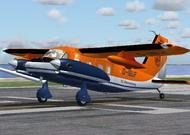
Aircraft used in the armed forces for more than ten countries around the world as a coherent and patrol. Equipped with two Pratt & Whitney turboprop RT6A-110 400 hp In my opinion worthy of attention plane.
→ Size:
12 MB
→ Date:
16 years ago (16.10.2009 20:46)
→ Author:
Mathias Elsaesser
→ Approved by moderator:
Lenya69
→ License:
Freeware - Free version, Unlimited Distribution
→ Downloaded:
2235 time(s)