The panel Boeing 707-320 Просмотр ZIP-архива
manual/starting.html
<!DOCTYPE HTML PUBLIC "-//SoftQuad//DTD HoTMetaL PRO 4.0::19971010::extensions to HTML 4.0//EN"
 "hmpro4.dtd">

<HTML>

  <HEAD>
    <META HTTP-EQUIV="Content-Type" CONTENT="text/html; charset=windows-1252">
    <TITLE>Boeing 707-320 Panel for FS2000/FS2002</TITLE>
  </HEAD>

  <BODY LINK="#0000ff" VLINK="#800080" BACKGROUND="clouds.gif">

    <P ALIGN="CENTER"><B><I><FONT FACE="Tahoma" SIZE="6">BOEING 707-320 -
      Engine Starting Guide</FONT></I></B></P>

    <P><FONT FACE="Tahoma" SIZE="6"><I>Introduction</I></FONT></P>

    <P>The engine starting procedure is based on that of the real aircraft, and
      is explained in this HTML file. Since the Boeing 707 lacks an APU, initial
      starting requires the aircraft to be hooked up to a power unit on the
      ground. In the simulation, this ground power unit is available whenever
      the aircraft is stationary. Diagrams are included to make this starting
      guide easier to use:</P>

    <P><FONT FACE="Tahoma" SIZE="6"><I>Starting the engines using the Ground
      Power Unit</I></FONT></P>

    <P>On a Boeing 707, the engines are normally started in the order 3-4-2-1.
      The starting procedure for is as follows: </P>
    <TABLE BGCOLOR="#99CCFF" WIDTH="90%" BORDER="1">
      <TR>
        <TD WIDTH="130" ALIGN="CENTER"><IMG SRC="extpoweron.jpg" ALT="External Power ON" WIDTH="110" HEIGHT="98"></TD>
        <TD><B>1. Hook-up Power from the Ground Power Unit</B> - the ground
        power unit provides electricity, plus the compressed air required for
        engine starting (on the Flight Engineer panel - set Num Lock off, then
        press SHIFT + Keypad 3).</TD>
      </TR>
      <TR>
        <TD WIDTH="130" ALIGN="CENTER"><IMG SRC="extelectselect.jpg" ALT="External Electric Power" WIDTH="110" HEIGHT="95"></TD>
        <TD><B>2. Set the Essential Power Switch to EXT</B> - this allows the
        ground power unit to supply electricity to the aircraft.</TD>
      </TR>
      <TR>
        <TD WIDTH="150" ALIGN="CENTER"><IMG SRC="lopress.jpg" ALT="Start Air Valve at Low Pressure" WIDTH="94" HEIGHT="74"></TD>
        <TD><B>3. Open the Start Air Valve</B> - this allows air from the
        ground power unit to reach the engine starters (return to the Pilot
        panel with SHIFT + Keypad 8, then bring up the Overhead panel with SHIFT
        + 7).</TD>
      </TR>
      <TR>
        <TD WIDTH="150" ALIGN="CENTER"><IMG SRC="startergnd.jpg" ALT="Engine 3 starter at GND" WIDTH="82" HEIGHT="74"></TD>
        <TD><B>4. Set the Engine 3 Start Control to GND</B> - This opens the
        flow of compressed air to the engine - you should see the N2 RPM begin
        to rise. </TD>
      </TR>
      <TR>
        <TD WIDTH="150" ALIGN="CENTER"><IMG SRC="leverstart.jpg" ALT="Start Lever at START" WIDTH="38" HEIGHT="44"></TD>
        <TD><B>5. Move the Engine 3 Start lever to START</B> (on the Throttle
        Quadrant - SHIFT + 6) - Once the N2 RPM reaches 15%, move the start
        lever (below the throttle) to START. This supplies fuel to the engine.
        </TD>
      </TR>
    </TABLE>

    <P>Once the engine is started, the start control moves to OFF, and the
      start lever moves to IDLE. Steps 4 and 5 may now be repeated for engine
      4,2 and 1. Once the procedure is completed, the Start Air Valve on the
      Overhead panel should be closed, the Essential Power Switch should be set
      to receive power from a running engine, and the Ground Power Unit should
      be disconnected.</P>

    <P><FONT FACE="Tahoma" SIZE="6"><I>Cross-bleed Starting</I></FONT></P>

    <P>Once one engine is started using the ground power unit, it is possible
      to use this engine to supply compressed air for starting other engines via
      a bleed or turbocompressor. The rest of the procedure for starting is the
      same as for starting using a ground power unit. </P>
    <TABLE BGCOLOR="#99CCFF" WIDTH="90%" BORDER="1">
      <TR>
        <TD WIDTH="150" ALIGN="CENTER"><IMG SRC="turbocompressor.jpg" ALT="Turbocompressor" WIDTH="80" HEIGHT="74"></TD>
        <TD><B>1. Check Engine Bleed is on, or Turbocompressor is running </B>-
        This is needed to supply compressed air to the engine starter. (check on
        the Flight Engineer panel)</TD>
      </TR>
      <TR>
        <TD WIDTH="130" ALIGN="CENTER"><IMG SRC="twoelectselect.jpg" ALT="Engine 2 Electric Power" WIDTH="110" HEIGHT="98"></TD>
        <TD><B>2. Check Electricity is Available</B> - set the Essential Power
        switch to obtain power from the already-running engine.</TD>
      </TR>
      <TR>
        <TD WIDTH="150" ALIGN="CENTER"><IMG SRC="lopress.jpg" ALT="Start Air Valve at Low Pressure" WIDTH="94" HEIGHT="74"></TD>
        <TD><B>3. Open the Start Air Valve</B> - this allows air from the
        ground power unit to reach the engine starters</TD>
      </TR>
      <TR>
        <TD WIDTH="150" ALIGN="CENTER"><IMG SRC="startergnd.jpg" ALT="Engine 3 starter at GND" WIDTH="82" HEIGHT="74"></TD>
        <TD><B>4. Set the Engine Start Control to GND</B> - This opens the
        flow of compressed air to the engine - you should see the N2 RPM begin
        to rise. </TD>
      </TR>
      <TR>
        <TD WIDTH="150" ALIGN="CENTER"><IMG SRC="leverstart.jpg" ALT="Start Lever at START" WIDTH="38" HEIGHT="44"></TD>
        <TD><B>5. Move the Start lever to START</B> - Once the N2 RPM reaches
        15%, move the start lever (below the throttle) to START. This supplies
        fuel to the engine. </TD>
      </TR>
    </TABLE>

    <P><FONT FACE="Tahoma" SIZE="6"><I>Windmill Starting</I></FONT></P>

    <P>If an engine fails in flight, this procedure is used to restart the
      engine. Unlike modern high-bypass turbofans, the JT3D is relatively easy
      to spin, and windmill starting is therefore possible at any airspeed above
      120 KIAS. </P>
    <TABLE BGCOLOR="#99CCFF" WIDTH="90%" BORDER="1">
      <TR>
        <TD WIDTH="150" ALIGN="CENTER"><IMG SRC="starterflt.jpg" ALT="Engine starter at FLT" WIDTH="82" HEIGHT="74"></TD>
        <TD><B>1. Set the Engine Start Control to FLT</B></TD>
      </TR>
      <TR>
        <TD WIDTH="150" ALIGN="CENTER"><IMG SRC="leverstart.jpg" ALT="Start Lever at START" WIDTH="38" HEIGHT="44"></TD>
        <TD><B>2. Move the Start lever to START</B> </TD>
      </TR>
    </TABLE>

    <P><A HREF="index.html">Back to Index</A></P>
  </BODY>
</HTML>
7072k2pn.zip
| Имя файла | Дата | Размер |
|---|---|---|
| gauges/ | 05.03.2003 00:35 | |
| gauges/707basics.gau | 08.01.2003 00:32 | 1 MB |
| gauges/707centre.gau | 25.01.2003 22:29 | 893 KB |
| gauges/707ENGINES.GAU | 04.03.2003 01:26 | 688 KB |
| gauges/707ENGINES2.GAU | 04.03.2003 01:26 | 688 KB |
| gauges/707flighteng.gau | 05.03.2003 00:53 | 1 MB |
| gauges/707gear.GAU | 16.08.2002 01:23 | 256 KB |
| gauges/707gear2.gau | 16.08.2002 01:25 | 256 KB |
| gauges/707gyros.gau | 05.01.2003 17:22 | 1 MB |
| gauges/707labels.gau | 25.01.2003 22:32 | 57 KB |
| gauges/707nightlight.gau | 05.01.2003 22:13 | 1019 KB |
| gauges/707nightlight2.gau | 05.01.2003 22:13 | 1016 KB |
| gauges/707omi.gau | 04.01.2003 21:57 | 55 KB |
| gauges/707omi2.gau | 04.01.2003 21:57 | 55 KB |
| gauges/707server.gau | 05.03.2003 00:26 | 1 MB |
| gauges/707wiper.gau | 16.08.2002 01:19 | 218 KB |
| panel/ | 05.03.2003 00:35 | |
| panel/autopilot.bmp | 12.08.2001 18:30 | 63 KB |
| panel/Captain.bmp | 05.01.2003 21:48 | 769 KB |
| panel/First-Officer.bmp | 05.01.2003 21:47 | 395 KB |
| panel/FORWARD_LEFT.BMP | 14.09.1999 07:02 | 341 KB |
| panel/FORWARD_RIGHT.BMP | 31.07.2002 02:16 | 514 KB |
| panel/forwardpanel.bmp | 02.01.2002 16:46 | 99 KB |
| panel/introscreen.bmp | 05.01.2003 15:16 | 351 KB |
| panel/LEFT.BMP | 14.09.1999 07:02 | 232 KB |
| panel/overhead.bmp | 23.02.2002 13:25 | 126 KB |
| panel/panel.cfg | 31.01.2003 23:27 | 6 KB |
| panel/REAR.BMP | 14.09.1999 07:02 | 703 KB |
| panel/REAR_LEFT.BMP | 14.09.1999 07:02 | 626 KB |
| panel/REAR_RIGHT.BMP | 31.07.2002 02:18 | 448 KB |
| panel/RIGHT.BMP | 12.02.2002 00:17 | 485 KB |
| panel/throttles.bmp | 25.09.2001 02:00 | 129 KB |
| panel/UP.BMP | 14.09.1999 07:02 | 289 KB |
| 707panel.jpg | 05.03.2003 01:06 | 306 KB |
| install.txt | 06.03.2003 01:33 | 778 B |
| manual/ | 05.03.2003 00:35 | |
| manual/707panel.jpg | 06.03.2003 01:47 | 106 KB |
| manual/adi.gif | 31.12.2001 00:11 | 18 KB |
| manual/airspeed.gif | 31.12.2001 16:53 | 6 KB |
| manual/altimeter.gif | 31.12.2001 00:15 | 8 KB |
| manual/autopilot.gif | 22.12.2001 14:10 | 15 KB |
| manual/basics.html | 29.07.2002 01:02 | 8 KB |
| manual/centre.html | 05.03.2003 01:02 | 5 KB |
| manual/clock.gif | 31.12.2001 16:54 | 6 KB |
| manual/Clouds.gif | 31.12.2001 21:33 | 74 KB |
| manual/controls.jpg | 31.12.2001 16:41 | 3 KB |
| manual/dme.jpg | 09.06.2002 18:33 | 3 KB |
| manual/electrics.gif | 01.02.2003 22:17 | 27 KB |
| manual/engines.jpg | 05.03.2003 00:58 | 58 KB |
| manual/engines2.jpg | 05.03.2003 00:59 | 32 KB |
| manual/extelectselect.jpg | 01.02.2003 22:17 | 4 KB |
| manual/extinguish.gif | 14.04.2002 18:08 | 8 KB |
| manual/extpoweron.jpg | 01.02.2003 22:19 | 3 KB |
| manual/fireoff.gif | 14.04.2002 18:08 | 7 KB |
| manual/firepulled.gif | 14.04.2002 18:08 | 7 KB |
| manual/flighteng.html | 01.02.2003 21:59 | 6 KB |
| manual/fuelpanel.jpg | 01.02.2003 22:08 | 30 KB |
| manual/hotbuttons.gif | 06.03.2003 01:34 | 126 KB |
| manual/hsi.jpg | 14.04.2002 17:23 | 11 KB |
| manual/index.html | 06.03.2003 01:33 | 7 KB |
| manual/INS.html | 29.07.2002 01:02 | 4 KB |
| manual/ins.jpg | 31.01.2002 00:55 | 18 KB |
| manual/leverstart.jpg | 30.04.2002 02:23 | 1 KB |
| manual/lighting1.jpg | 30.04.2002 00:06 | 33 KB |
| manual/lighting2.jpg | 30.04.2002 00:06 | 36 KB |
| manual/lighting3.jpg | 30.04.2002 00:06 | 36 KB |
| manual/lightswitches.gif | 31.12.2001 17:51 | 5 KB |
| manual/lopress.jpg | 30.04.2002 02:20 | 3 KB |
| manual/mach.gif | 31.12.2001 16:21 | 4 KB |
| manual/overhead.gif | 30.04.2002 00:12 | 36 KB |
| manual/overhead.html | 09.09.2002 01:29 | 5 KB |
| manual/pitotheat.gif | 30.04.2002 00:11 | 4 KB |
| manual/pressurization.jpg | 14.04.2002 17:36 | 34 KB |
| manual/radalt.gif | 31.12.2001 16:54 | 6 KB |
| manual/revclosed.gif | 14.04.2002 18:08 | 1 KB |
| manual/revopen.gif | 14.04.2002 18:07 | 2 KB |
| manual/revopening.gif | 14.04.2002 18:07 | 1 KB |
| manual/rmi1.jpg | 31.12.2001 16:32 | 6 KB |
| manual/rmi2.jpg | 31.12.2001 16:32 | 6 KB |
| manual/rmi3.jpg | 31.12.2001 16:32 | 6 KB |
| manual/rmi4.jpg | 31.12.2001 16:32 | 6 KB |
| manual/speeds.html | 02.02.2003 01:17 | 24 KB |
| manual/starterflt.jpg | 30.04.2002 02:39 | 3 KB |
| manual/startergnd.jpg | 30.04.2002 02:22 | 3 KB |
| manual/starters.gif | 30.04.2002 00:09 | 7 KB |
| manual/starting.html | 01.02.2003 22:26 | 6 KB |
| manual/throttles.html | 01.02.2003 22:36 | 4 KB |
| manual/throttquad.gif | 01.02.2003 22:35 | 66 KB |
| manual/trueairspeed.jpg | 14.04.2002 17:26 | 4 KB |
| manual/turbocompressor.jpg | 30.04.2002 02:33 | 3 KB |
| manual/turncoord.jpg | 14.04.2002 17:17 | 3 KB |
| manual/twoelectselect.jpg | 01.02.2003 22:24 | 4 KB |
| manual/unlit.jpg | 30.04.2002 00:06 | 25 KB |
| avsim_ru.diz | 14.03.2004 00:14 | 457 B |
| Итого: | 16 MB | |
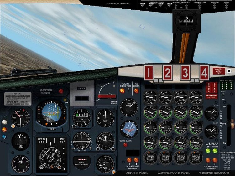
The panel for the Boeing 707-320 aircraft version 3.0. Includes panel captain, second pilot and engineer. Instruction in the archive.
→ Size:
6 MB
→ Date:
23 years ago (07.03.2003 11:58)
→ Author:
George Carty
→ License:
Freeware - Free version, Unlimited Distribution
→ Downloaded:
303 time(s)