The panel Boeing 707-320 Просмотр ZIP-архива
manual/basics.html
<!DOCTYPE HTML PUBLIC "-//SoftQuad//DTD HoTMetaL PRO 4.0::19971010::extensions to HTML 4.0//EN"
 "hmpro4.dtd">

<HTML>

  <HEAD>
    <META HTTP-EQUIV="Content-Type" CONTENT="text/html; charset=windows-1252">
    <TITLE>Boeing 707-320 Panel for FS2000/FS2002</TITLE>
  </HEAD>

  <BODY LINK="#0000ff" VLINK="#800080" BACKGROUND="clouds.gif">

    <P ALIGN="CENTER"><B><I><FONT FACE="Tahoma" SIZE="6">BOEING 707-320
      panel - Basic Flight Instruments</FONT></I></B> </P>

    <P><B>The Airspeed and Mach Indicators</B></P>

    <P><IMG SRC="airspeed.gif" ALT="Airspeed indicator" ALIGN="LEFT" WIDTH="105" HEIGHT="105">The
      Boeing 707 airspeed indicator has a slightly different scale to the ASI in
      the default FS2000/FS2002 737, and this panel reflects this. You may also note
      that the instrument has no digital readouts whatsoever. The airspeed
      indicator contains a speed bug which may be useful as a reference when
      taking off or landing. However, the only place on the panel where the
      speed bug has an effect is the Fast/Slow gauge on the ADI - the 707 is not
      equipped with an autothrottle. <IMG SRC="mach.gif" ALT="Mach meter" ALIGN="RIGHT" WIDTH="100" HEIGHT="100"></P>

    <P ALIGN="LEFT">Since there is no Mach reading on the ASI, a separate Mach
      meter is required - it is located below the Turn Co-ordinator. Since the
      707 is a subsonic aircraft, the scale of the Mach meter ends at 1.0.</P>
    <TABLE WIDTH="90%">
      <TR>
        <TD WIDTH="120"><IMG SRC="altimeter.gif" ALT="Image of altimeter" ALIGN="MIDDLE" WIDTH="118" HEIGHT="114"></TD>
        <TD>

        <P><B>The Altimeter</B></P>

        <P>This panel's altimeter is in fact quite modern, in that it displays
          a digital reading of the entire altitude, by means of rotating drums
          (In 707s from a few years earlier, only the thousands were displayed
          numerically). The gauge also displays its pressure setting by means of
          numeric drum readouts, in both imperial and metric units.</P></TD>
      </TR>
    </TABLE>
    <TABLE WIDTH="90%">
      <TR>
        <TD>

        <P><B>The Radio Altimeter</B></P>

        <P>This instrument indicates the aircraft's height above the ground,
          and is useful for judging the approach to the ground when landing. The
          instrument reads as far as 2,500 ft, and contains an adjustable
          Decision Height bug - when the decision height is reached, the DH
          light on the ADI will come on momentarily.</P> </TD>
        <TD WIDTH="120"><IMG SRC="radalt.gif" ALT="Radio altimeter" ALIGN="MIDDLE" WIDTH="110" HEIGHT="110"></TD>
      </TR>
    </TABLE>
    <TABLE WIDTH="90%">
      <TR>
        <TD WIDTH="250"><IMG SRC="rmi1.jpg" ALT="Image of RMI" ALIGN="MIDDLE" WIDTH="110" HEIGHT="110">
        <IMG SRC="rmi2.jpg" ALIGN="MIDDLE" WIDTH="110" HEIGHT="110"> <BR>
        <IMG SRC="rmi3.jpg" ALIGN="MIDDLE" WIDTH="110" HEIGHT="110">
        <IMG SRC="rmi4.jpg" ALIGN="MIDDLE" WIDTH="110" HEIGHT="110"></TD>
        <TD>

        <P><B>The RMI</B></P>

        <P>This instrument on the Captain's panel has two switches, permitting
          the needles to be switched between pointing to the VOR, or the ADF.
          Since there is only one ADF available in FS2000/FS2002, when both needles are
          set to ADF, they will point in the same direction. <BR>
           Directly below the RMI is the DME 2 readout, giving the distance to
          the NAV 2 beacon. The distance to the NAV 1 beacon is given on the
          HSI.</P></TD>
      </TR>
    </TABLE>
    <TABLE WIDTH="90%">
      <TR>
        <TD>

        <P><B>The DME</B></P>

        <P>Below the RMI, there is a readout for the distance to DME 2 (the DME
          1 readout is on the HSI).</P> </TD>
        <TD WIDTH="120"><IMG SRC="dme.jpg" ALT="DME" ALIGN="MIDDLE" WIDTH="98" HEIGHT="77">
        </TD>
      </TR>
    </TABLE>
    <TABLE WIDTH="90%">
      <TR>
        <TD WIDTH="110"><IMG SRC="turncoord.jpg" ALT="Turn Co-ordinator" ALIGN="MIDDLE" WIDTH="102" HEIGHT="102"></TD>
        <TD>

        <P><B>The Turn Co-ordinator</B></P>

        <P>This instrument is in some ways a hangover from the instrument
          panels of piston-engined aircraft - the needle indicates the rate of
          turn, while the ball indicates slipping or skidding of the aircraft.
          If you have Auto-Coordination switched on in FS2000/FS2002, the ball will
          always be centred.</P></TD>
      </TR>
    </TABLE>
    <TABLE WIDTH="90%">
      <TR>
        <TD>

        <P><B>The Clock</B></P>

        <P>The 707 is fitted with an analogue clock with hour, minute and
          second hands. To adjust the clock, there is a knob at the lower right
          which increments/decrements by 1 minute per click. When passing
          through zero, the hours change accordingly, as with a real analogue
          clock. However, to speed up setting time, there is an extra knob at
          the lower left which adjusts hours directly. Note the small inset
          clock above the main clock - this reads Zulu Time.</P> </TD>
        <TD WIDTH="120"><IMG SRC="clock.gif" ALT="Clock" ALIGN="MIDDLE" WIDTH="102" HEIGHT="102">
        </TD>
      </TR>
    </TABLE>
    <TABLE WIDTH="90%">
      <TR>
        <TD WIDTH="110"><IMG SRC="controls.jpg" ALT="Image of RMI" ALIGN="MIDDLE" WIDTH="100" HEIGHT="100"></TD>
        <TD>

        <P><B>The Flight Control Positions Indicator</B></P>

        <P>This instrument, located on the First Officer's panel, indicates the
          position of the flight controls. When the control column or autopilot
          are commanding a roll to the left, the aileron position indicator
          rolls right - this symbolizes the movement of the ailerons up on the
          left hand side of the aircraft, and down on the right hand side.</P></TD>
      </TR>
    </TABLE>

    <P><B>The ADI</B> </P>
    <TABLE WIDTH="90%">
      <TR>
        <TD>

        <P>This ADI layout was used on most US-built airliners from the mid-60s
          up until the 1980s, when EFIS computer displays began to take over. In
          addition to the attitude indicator, the ADI contains the following
          components:</P>
        <UL>
          <LI><B>Fast-Slow Gauge</B>- to the left of the attitude indicator
            this indicates the aircraft's airspeed, relative to the speed
            selected with the airspeed bug. Each dot on the scale represents 10
            knots.</LI>
          <LI><B>Localizer and Glideslope indicators</B> - located below and
            to the right of the attitude indicator respectively, these indicate
            the aircraft's position relative to an ILS beam. This information is
            also available on the HSI.</LI>
          <LI><B>Decision Height Light</B> - comes on momentarily when
            descending through the Decision Height.</LI>
          <LI><B>Flight Director</B> - allows the autopilot to give commands
            to the pilot, rather than flying the aircraft directly. This is
            integrated with all of the autopilot's modes, but is most useful
            during the landing approach.</LI>
        </UL> </TD>
        <TD WIDTH="200"><IMG SRC="adi.gif" ALT="Image of ADI" ALIGN="MIDDLE" WIDTH="185" HEIGHT="185"></TD>
      </TR>
    </TABLE>

    <P>The presentation of various types of information in one location makes
      the ADI helpful when carrying out an instrument approach and landing. </P>
    <TABLE WIDTH="90%">
      <TR>
        <TD WIDTH="110"><IMG SRC="hsi.jpg" ALT="Image of HSI" ALIGN="MIDDLE" WIDTH="166" HEIGHT="187"></TD>
        <TD>

        <P><B>The HSI</B></P>

        <P>The HSI has the standard layout for pre-EFIS jet aircraft. Note the
          setting knobs on the instrument - the left one sets the OBS course,
          while the right one sets the target heading for the autopilot (newer
          aircraft models have these controls in the autopilot on the
          glareshield). The instrument also has numeric readouts for the current
          OBS course, and DME 1.</P></TD>
      </TR>
    </TABLE>

    <P><A HREF="index.html">Back to Index</A></P>
  </BODY>
</HTML>
7072k2pn.zip
| Имя файла | Дата | Размер |
|---|---|---|
| gauges/ | 05.03.2003 00:35 | |
| gauges/707basics.gau | 08.01.2003 00:32 | 1 MB |
| gauges/707centre.gau | 25.01.2003 22:29 | 893 KB |
| gauges/707ENGINES.GAU | 04.03.2003 01:26 | 688 KB |
| gauges/707ENGINES2.GAU | 04.03.2003 01:26 | 688 KB |
| gauges/707flighteng.gau | 05.03.2003 00:53 | 1 MB |
| gauges/707gear.GAU | 16.08.2002 01:23 | 256 KB |
| gauges/707gear2.gau | 16.08.2002 01:25 | 256 KB |
| gauges/707gyros.gau | 05.01.2003 17:22 | 1 MB |
| gauges/707labels.gau | 25.01.2003 22:32 | 57 KB |
| gauges/707nightlight.gau | 05.01.2003 22:13 | 1019 KB |
| gauges/707nightlight2.gau | 05.01.2003 22:13 | 1016 KB |
| gauges/707omi.gau | 04.01.2003 21:57 | 55 KB |
| gauges/707omi2.gau | 04.01.2003 21:57 | 55 KB |
| gauges/707server.gau | 05.03.2003 00:26 | 1 MB |
| gauges/707wiper.gau | 16.08.2002 01:19 | 218 KB |
| panel/ | 05.03.2003 00:35 | |
| panel/autopilot.bmp | 12.08.2001 18:30 | 63 KB |
| panel/Captain.bmp | 05.01.2003 21:48 | 769 KB |
| panel/First-Officer.bmp | 05.01.2003 21:47 | 395 KB |
| panel/FORWARD_LEFT.BMP | 14.09.1999 07:02 | 341 KB |
| panel/FORWARD_RIGHT.BMP | 31.07.2002 02:16 | 514 KB |
| panel/forwardpanel.bmp | 02.01.2002 16:46 | 99 KB |
| panel/introscreen.bmp | 05.01.2003 15:16 | 351 KB |
| panel/LEFT.BMP | 14.09.1999 07:02 | 232 KB |
| panel/overhead.bmp | 23.02.2002 13:25 | 126 KB |
| panel/panel.cfg | 31.01.2003 23:27 | 6 KB |
| panel/REAR.BMP | 14.09.1999 07:02 | 703 KB |
| panel/REAR_LEFT.BMP | 14.09.1999 07:02 | 626 KB |
| panel/REAR_RIGHT.BMP | 31.07.2002 02:18 | 448 KB |
| panel/RIGHT.BMP | 12.02.2002 00:17 | 485 KB |
| panel/throttles.bmp | 25.09.2001 02:00 | 129 KB |
| panel/UP.BMP | 14.09.1999 07:02 | 289 KB |
| 707panel.jpg | 05.03.2003 01:06 | 306 KB |
| install.txt | 06.03.2003 01:33 | 778 B |
| manual/ | 05.03.2003 00:35 | |
| manual/707panel.jpg | 06.03.2003 01:47 | 106 KB |
| manual/adi.gif | 31.12.2001 00:11 | 18 KB |
| manual/airspeed.gif | 31.12.2001 16:53 | 6 KB |
| manual/altimeter.gif | 31.12.2001 00:15 | 8 KB |
| manual/autopilot.gif | 22.12.2001 14:10 | 15 KB |
| manual/basics.html | 29.07.2002 01:02 | 8 KB |
| manual/centre.html | 05.03.2003 01:02 | 5 KB |
| manual/clock.gif | 31.12.2001 16:54 | 6 KB |
| manual/Clouds.gif | 31.12.2001 21:33 | 74 KB |
| manual/controls.jpg | 31.12.2001 16:41 | 3 KB |
| manual/dme.jpg | 09.06.2002 18:33 | 3 KB |
| manual/electrics.gif | 01.02.2003 22:17 | 27 KB |
| manual/engines.jpg | 05.03.2003 00:58 | 58 KB |
| manual/engines2.jpg | 05.03.2003 00:59 | 32 KB |
| manual/extelectselect.jpg | 01.02.2003 22:17 | 4 KB |
| manual/extinguish.gif | 14.04.2002 18:08 | 8 KB |
| manual/extpoweron.jpg | 01.02.2003 22:19 | 3 KB |
| manual/fireoff.gif | 14.04.2002 18:08 | 7 KB |
| manual/firepulled.gif | 14.04.2002 18:08 | 7 KB |
| manual/flighteng.html | 01.02.2003 21:59 | 6 KB |
| manual/fuelpanel.jpg | 01.02.2003 22:08 | 30 KB |
| manual/hotbuttons.gif | 06.03.2003 01:34 | 126 KB |
| manual/hsi.jpg | 14.04.2002 17:23 | 11 KB |
| manual/index.html | 06.03.2003 01:33 | 7 KB |
| manual/INS.html | 29.07.2002 01:02 | 4 KB |
| manual/ins.jpg | 31.01.2002 00:55 | 18 KB |
| manual/leverstart.jpg | 30.04.2002 02:23 | 1 KB |
| manual/lighting1.jpg | 30.04.2002 00:06 | 33 KB |
| manual/lighting2.jpg | 30.04.2002 00:06 | 36 KB |
| manual/lighting3.jpg | 30.04.2002 00:06 | 36 KB |
| manual/lightswitches.gif | 31.12.2001 17:51 | 5 KB |
| manual/lopress.jpg | 30.04.2002 02:20 | 3 KB |
| manual/mach.gif | 31.12.2001 16:21 | 4 KB |
| manual/overhead.gif | 30.04.2002 00:12 | 36 KB |
| manual/overhead.html | 09.09.2002 01:29 | 5 KB |
| manual/pitotheat.gif | 30.04.2002 00:11 | 4 KB |
| manual/pressurization.jpg | 14.04.2002 17:36 | 34 KB |
| manual/radalt.gif | 31.12.2001 16:54 | 6 KB |
| manual/revclosed.gif | 14.04.2002 18:08 | 1 KB |
| manual/revopen.gif | 14.04.2002 18:07 | 2 KB |
| manual/revopening.gif | 14.04.2002 18:07 | 1 KB |
| manual/rmi1.jpg | 31.12.2001 16:32 | 6 KB |
| manual/rmi2.jpg | 31.12.2001 16:32 | 6 KB |
| manual/rmi3.jpg | 31.12.2001 16:32 | 6 KB |
| manual/rmi4.jpg | 31.12.2001 16:32 | 6 KB |
| manual/speeds.html | 02.02.2003 01:17 | 24 KB |
| manual/starterflt.jpg | 30.04.2002 02:39 | 3 KB |
| manual/startergnd.jpg | 30.04.2002 02:22 | 3 KB |
| manual/starters.gif | 30.04.2002 00:09 | 7 KB |
| manual/starting.html | 01.02.2003 22:26 | 6 KB |
| manual/throttles.html | 01.02.2003 22:36 | 4 KB |
| manual/throttquad.gif | 01.02.2003 22:35 | 66 KB |
| manual/trueairspeed.jpg | 14.04.2002 17:26 | 4 KB |
| manual/turbocompressor.jpg | 30.04.2002 02:33 | 3 KB |
| manual/turncoord.jpg | 14.04.2002 17:17 | 3 KB |
| manual/twoelectselect.jpg | 01.02.2003 22:24 | 4 KB |
| manual/unlit.jpg | 30.04.2002 00:06 | 25 KB |
| avsim_ru.diz | 14.03.2004 00:14 | 457 B |
| Итого: | 16 MB | |
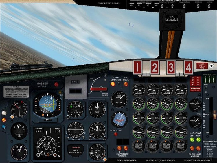
The panel for the Boeing 707-320 aircraft version 3.0. Includes panel captain, second pilot and engineer. Instruction in the archive.
→ Size:
6 MB
→ Date:
23 years ago (07.03.2003 11:58)
→ Author:
George Carty
→ License:
Freeware - Free version, Unlimited Distribution
→ Downloaded:
303 time(s)